Toyota Venza: System Description
SYSTEM DESCRIPTION
1. GENERAL
(a) Deceleration sensors used for the airbag system are installed on various parts on the vehicle and calculate the deceleration rate of each part during a collision.
(b) Depending on the situation, the center airbag sensor assembly sends a deployment signal to airbag and pretensioner based on the information from each sensor.
2. DEPLOYMENT CONDITION
(a) FRONTAL COLLISION
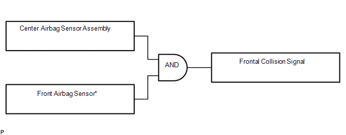
(1) Frontal collision signals are produced based on the information from the center airbag sensor assembly and front airbag sensors.
HINT:
*: In case of a frontal collision, the SRS ignition signal could be output with the deceleration sensor ON signal even without a signal from the front airbag sensors.
(2) Frontal collision signals are used to deploy the airbags and pretensioners except the side airbags.
(b) SIDE COLLISION (1)
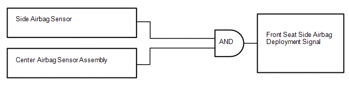
(1) The side airbags are deployed based on signals from the side airbag sensors and center airbag sensor assembly.
HINT:
The curtain shield airbags and front pretensioners are deployed at the same time.
(c) SIDE COLLISION (2)
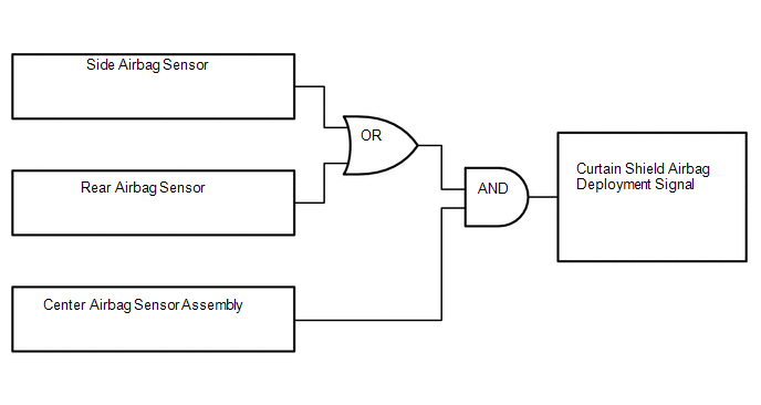
(1) The curtain shield airbags are deployed when both of the following conditions are met:
- Signals from the side airbag sensors or rear airbag sensors are received.
- Signal from the center airbag sensor assembly is received.
 How To Proceed With Troubleshooting
CAUTION / NOTICE / HINT
HINT:
*: Use the Techstream.
PROCEDURE
1.
VEHICLE BROUGHT TO WORKSHOP
NEXT
...
 Problem Symptoms Table
PROBLEM SYMPTOMS TABLE
HINT:
Use the table below to help determine the cause of problem symptoms.
If multiple suspected areas are listed, the potential causes of the symptoms
are lis ...
Other materials about Toyota Venza:
Pressure Control Solenoid "B" Performance (Shift Solenoid Valve SL2) (P0776)
SYSTEM DESCRIPTION
The TCM uses the vehicle speed signal and signals from the transmission speed
sensors (NC, NT) to detect the actual gear (1st, 2nd, 3rd, 4th, 5th or 6th gear).
Then the TCM compares the actual gear with the shift schedule in the TCM memo ...
Fuel Injector Circuit
DESCRIPTION
The fuel injector assemblies are located on the intake manifold. They inject
fuel into the cylinders based on signals from the ECM.
WIRING DIAGRAM
CAUTION / NOTICE / HINT
NOTICE:
Inspect the fuses for circuits related to this system befo ...
Intake Air Control Valve Actuator(for Tcv)
Components
COMPONENTS
ILLUSTRATION
Removal
REMOVAL
PROCEDURE
1. REMOVE INTAKE MANIFOLD
(a) Remove the intake manifold (See page ).
2. REMOVE INTAKE AIR CONTROL VALVE ACTUATOR (for TCV)
(a) Remove the 2 bolts, intake air control valve actuator a ...

0.152