Toyota Venza: Door Side Airbag Sensor RH Malfunction (B1690/15)
DESCRIPTION
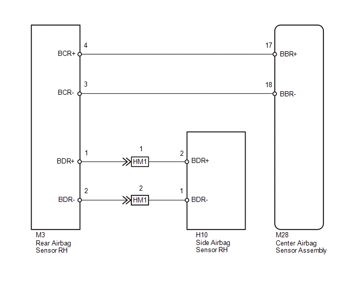
The side collision sensor RH circuit (to determine deployment of the front seat side airbag assembly RH and curtain shield airbag assembly RH) is composed of the center airbag sensor assembly, rear airbag sensor RH and side airbag sensor RH.
The side airbag sensor RH detect impacts to the vehicle and send signals to the center airbag sensor assembly to determine if the airbag should be deployed.
DTC B1690/15 is stored when a malfunction is detected in the side airbag sensor RH.
|
DTC No. |
DTC Detection Condition |
Trouble Area |
|---|---|---|
|
B1690/15 |
|
|
WIRING DIAGRAM
PROCEDURE
|
1. |
CHECK SIDE AIRBAG SENSOR RH |
|
(a) Turn the ignition switch off. |
|
(b) Disconnect the cable from the negative (-) battery terminal, and wait for at least 90 seconds.
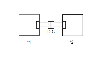
(c) Interchange the side airbag sensor LH with RH and connect the connectors.
(d) Connect the cable to the negative (-) battery terminal.
(e) Turn the ignition switch to ON, and wait for at least 60 seconds.
(f) Clear the DTCs stored in memory (See page
.gif) ).
).
(g) Turn the ignition switch off.
(h) Turn the ignition switch to ON, and wait for at least 60 seconds.
(i) Check for DTCs (See page ).
|
Result |
Proceed to |
|---|---|
|
DTC B1690/15 is output. |
A |
|
DTC B1695/16 is output. |
B |
|
DTCs B1690/15 and B1695/16 are not output. |
C |
|
*1 |
Side Airbag Sensor LH |
|
*2 |
Rear Airbag Sensor RH |
HINT:
Codes other than DTCs B1690/15 and B1695/16 may be output at this time, but they are not related to this check.
| A | .gif) |
REPLACE CENTER AIRBAG SENSOR ASSEMBLY |
| B | |
REPLACE SIDE AIRBAG SENSOR RH |
| C | |
USE SIMULATION METHOD TO CHECK |
 Passenger Airbag ON/OFF Indicator Circuit Malfunction (B1660/43)
DESCRIPTION
The passenger airbag ON/OFF indicator circuit consists of the center airbag sensor
assembly and accessory meter assembly (passenger airbag ON/OFF indicator).
The passenger airbag ON/OF ...
 Door Side Airbag Sensor LH Malfunction (B1695/16)
DESCRIPTION
The side collision sensor LH circuit (to determine deployment of the front seat
side airbag assembly LH and curtain shield airbag assembly LH) is composed of the
center airbag sensor ...
Other materials about Toyota Venza:
How To Proceed With Troubleshooting
PROCEDURE
1.
CHECK TIRE AND WHEEL SYSTEM
DIAGNOSIS OF IRREGULAR TIRE WEAR
GO TO STEP 11
DIAGNOSIS OF TIRE VIBRATION
2.
...
Installation
INSTALLATION
CAUTION / NOTICE / HINT
HINT:
Use the same procedure for the RH side and LH side.
The procedure listed below is for the LH side.
PROCEDURE
1. INSTALL REAR STRUT ROD ASSEMBLY (for 2WD)
(a) Temporarily install the ...
Inspection
INSPECTION
PROCEDURE
1. INSPECT DRIVER SIDE LUMBAR SWITCH
(a) Measure the resistance between the terminals when the switch is operated.
Standard Resistance:
Tester Connection
Switch Condition
...

0.1436