Toyota Venza: Dtc Check / Clear
DTC CHECK / CLEAR
1. CHECK DTC (CHECK USING TECHSTREAM)
(a) Connect the Techstream to the DLC3.
(b) Turn the ignition switch to ON.
(c) Turn the Techstream on.
(d) Enter the following menus: Body Electrical / Navigation System / Trouble Codes.
(e) Check for DTCs, and then write them down.
(f) Check the details of the DTC(s) (See page
.gif) ).
).
NOTICE:
The navigation system outputs DTCs for the following system. When DTCs other than those in Diagnostic Trouble Code Chart for the navigation system are output, refer to Diagnostic Trouble Code Chart for the relevant system.
|
System |
Proceed to |
|---|---|
|
Rear View Monitor System |
|
2. CLEAR DTC (CLEAR USING TECHSTREAM)
(a) Connect the Techstream to the DLC3.
(b) Turn the ignition switch to ON.
(c) Turn the Techstream on.
(d) Enter the following menus: Body Electrical / Navigation System / Trouble Codes.
(e) Clear the DTCs.
3. START DIAGNOSTIC MODE
HINT:
- Illustrations may differ from the actual vehicle screen depending on the device settings and options. Therefore, some detailed areas may not be shown exactly the same as on the actual vehicle screen.
- If the system cannot enter diagnostic mode, inspect all AVC-LAN communication
components and repair or replace malfunctioning parts (for 13 Speakers)
(See page ).
- After the ignition switch is turned to ON, check that the map is displayed before starting diagnostic mode. Otherwise, some items cannot be checked.
(a) Turn the ignition switch to ON.
(b) While pressing and holding the "AUDIO" switch, operate the light control switch: Off → Tail → Off → Tail → Off → Tail → Off.
(c) Diagnostic mode starts and the "Service Menu" screen will be displayed. Service inspection starts automatically and the result will be displayed.
4. FAILURE DIAGNOSIS
(a) The "Failure Diagnosis" screen will be displayed by selecting "Failure Diagnosis" on the "Service Menu" screen.
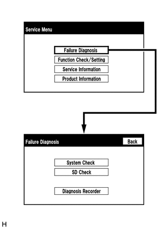
5. SYSTEM CHECK
(a) The "System Check Mode" screen will be displayed by selecting "System Check" on the "Failure Diagnosis" screen.
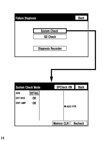
6. CHECK DTC (CHECK USING SYSTEM CHECK MODE SCREEN)
(a) System check mode screen description
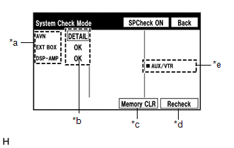 Screen Description
|
Display |
Content |
|---|---|
|
*a: Device name list No. 1 |
|
|
*b: Check result |
Result codes for all devices are displayed. |
|
*c: Memory clear |
|
|
*d: Recheck |
|
|
*e: Device name list No. 2 |
|
|
Name |
Component |
Connection Method |
|---|---|---|
|
AVN |
Navigation receiver assembly |
- |
|
EXT BOX*1 |
Stereo component tuner assembly |
LVDS communication line |
|
DSP-AMP*2 |
Stereo component amplifier assembly |
AVC-LAN communication line |
- *1: w/ SDARS System
- *2: for 13 Speakers
|
Result |
Meaning |
Action |
|---|---|---|
|
OK |
The device does not respond with a DTC. |
- |
|
DETAIL |
The device responds with a DTC. |
Read the DTC on the "Unit Check Mode" screen. |
|
NCON*1*2 |
The device was previously present, but does not respond in diagnostic mode. |
- Check the power supply circuit of the device. - Check the communication line of the device. |
|
NRES*1*2 |
The device responds in diagnostic mode, but gives no DTC information. |
- Check the power supply circuit of the device. - Check the communication line of the device. |
- *1: w/ SDARS System
- *2: for 13 Speakers
HINT:
When "NCON" is displayed for all devices connected through the AVC-LAN, or when
all device names are not displayed, check if there is a short in an AVC-LAN line
or devices connected to the AVC-LAN. Repair or replace parts as necessary (for 13
Speakers) (See page ).
*e: Device Name List No. 2 Description
|
Name |
Component |
Connection Method |
|---|---|---|
|
AUX/VTR |
No. 1 stereo jack adapter assembly |
Vehicle wire harness |
(b) Unit check mode screen description
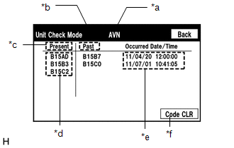 Screen Description
|
Display |
Content |
|---|---|
|
*a: Device name |
Target device |
|
*b: History DTC |
Diagnostic memory results and stored DTCs are displayed. |
|
*c: Current DTC |
DTCs output in the service check are displayed. |
|
*d: DTC |
DTC (Diagnostic Trouble Code) |
|
*e: Timestamp |
The time and date of history DTCs are displayed. (The year is displayed in 2-digit format.) |
|
*f: Diagnosis clear |
Selecting "Code CLR" for 3 seconds clears the diagnostic memory data of the target device. (Both diagnostic system check result and the displayed data are cleared.) |
HINT:
- This screen is updated once per second.
- A maximum of 6 DTCs can be displayed for history and present DTCs.
(c) Read the system check result.

(1) If the check result is "DETAIL", select the displayed check result to view the results on the "Unit Check Mode" screen and record them.
NOTICE:
A maximum of 6 DTCs can be displayed for history and present DTCs on the "Unit Check Mode" screen. Therefore, when 6 DTCs are displayed, troubleshoot those DTCs first and then check the "Unit Check Mode" screen again to see if any other DTCs are displayed.
HINT:
- When all results are "OK", no DTCs are present.
- When proceeding to view the results of another device, select "Back" to return to the "System Check Mode" screen. Repeat the above step to view the results of other devices.
(2) Check the details of the DTC(s) (See page
).
NOTICE:
The navigation system outputs DTCs for the following system. When DTCs other than those in Diagnostic Trouble Code Chart for the navigation system are output, refer to Diagnostic Trouble Code Chart for the relevant system.
|
System |
Proceed to |
|---|---|
|
Rear View Monitor System |
|
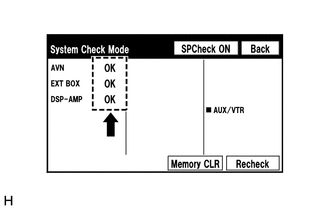
7. DTC CLEAR/RECHECK (CLEAR USING SYSTEM CHECK MODE SCREEN)
(a) Clear DTCs
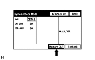
(1) Select "Memory CLR" for 3 seconds.
(2) Confirm that the check results are cleared.
HINT:
- To clear the DTCs for a specific device, use the "Unit Check Mode" screen.
- When clearing the DTCs using the "Unit Check Mode" screen, select "Code CLR" for 3 seconds.
(b) Recheck
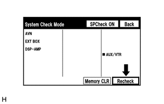
(1) Select "Recheck".
(2) Confirm that all diagnostic codes are "OK" when the check results are displayed. If a result other than "OK" is displayed, perform troubleshooting again.
HINT:
When the DTCs are cleared using the "Unit Check Mode" screen, select "Back" to return to the "System Check Mode" screen and perform this operation.
8. FINISH DIAGNOSTIC MODE
(a) Turn the ignition switch off.
 Terminals Of Ecu
TERMINALS OF ECU
HINT:
Check from the rear of the connector while it is connected to the components.
1. NAVIGATION RECEIVER ASSEMBLY
Terminal No. (Symbol)
Wiring Color
...
 Data List / Active Test
DATA LIST / ACTIVE TEST
1. DATA LIST
NOTICE:
In the table below, the values listed under "Normal Condition" are reference
values. Do not depend solely on these reference values when dec ...
Other materials about Toyota Venza:
Fuel Receiver Gauge Malfunction
DESCRIPTION
The meter CPU uses the fuel sender gauge assembly to determine the level
of the fuel in the fuel tank. The resistance of the fuel sender gauge will
vary between approximately 7.5 Ω with the float at the full position, and
185 Î ...
Diagnostic Trouble Code Chart
DIAGNOSTIC TROUBLE CODE CHART
Navigation System
DTC Code
Detection Item
See page
B1532
LVDS Signal Malfunction (from Extension Module)
B1551
HD Radio Tuner ...
Dtc Check / Clear
DTC CHECK / CLEAR
NOTICE:
When the diagnosis system is changed from normal mode to check mode or vice versa,
all DTCs and freeze frame data recorded in normal mode are cleared. Before changing
modes, always check and make a note of DTCs and freeze frame ...

0.1643