Toyota Venza: Brake Warning Light Remains ON
DESCRIPTION
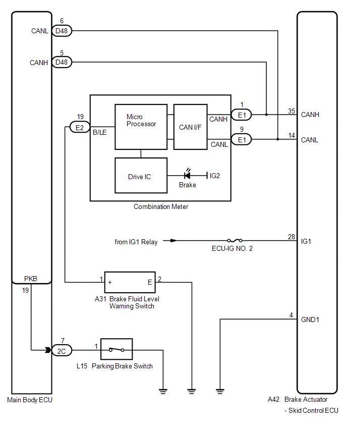
The skid control ECU is connected to the combination meter via CAN communication.
If any of the following is detected, the brake warning light remains on:
- The skid control ECU connector is disconnected from the skid control ECU.
- The brake fluid level is insufficient.
- The parking brake is applied.
- EBD operation is not possible.
WIRING DIAGRAM
PROCEDURE
|
1. |
CHECK CAN COMMUNICATION SYSTEM |
(a) Check if a CAN communication system DTC is output (See page
.gif) ).
).
|
Result |
Proceed to |
|---|---|
|
DTC is not output |
A |
|
DTC is output |
B |
| B | .gif) |
INSPECT CAN COMMUNICATION SYSTEM |
|
.gif)
|
2. |
CHECK IF SKID CONTROL ECU CONNECTOR IS SECURELY CONNECTED |
(a) Check if the skid control ECU connector is securely connected.
OK:
The connector is securely connected.
| NG | |
CONNECT CONNECTOR TO ECU CORRECTLY |
|
|
3. |
CHECK BATTERY |
(a) Check the battery voltage.
Standard Voltage:
11 to 14 V
|
Result |
Proceed to |
|---|---|
|
OK |
A |
|
NG (for 2GR-FE) |
B |
|
NG (for 1AR-FE) |
C |
| B | |
CHECK OR REPLACE CHARGING SYSTEM OR BATTERY (for 2GR-FE) |
| C | |
CHECK OR REPLACE CHARGING SYSTEM OR BATTERY (for 1AR-FE) |
|
|
4. |
INSPECT SKID CONTROL ECU (IG1 TERMINAL) |
|
(a) Disconnect the skid control ECU connector. |
|
.png)
(b) Turn the ignition switch to ON.
(c) Measure the voltage according to the value(s) in the table below.
Standard Voltage:
|
Tester Connection |
Switch Condition |
Specified Condition |
|---|---|---|
|
A42-28 (IG1) - Body ground |
Ignition switch ON |
11 to 14 V |
|
*1 |
Front view of wire harness connector (to Brake Actuator (Skid Control ECU)) |
| NG | |
REPAIR OR REPLACE HARNESS OR CONNECTOR (IG1 CIRCUIT) |
|
|
5. |
INSPECT SKID CONTROL ECU (GND1 TERMINAL) |
|
(a) Turn the ignition switch off. |
|
.png)
(b) Measure the resistance according to the value(s) in the table below.
Standard Resistance:
|
Tester Connection |
Condition |
Specified Condition |
|---|---|---|
|
A42-4 (GND1) - Body ground |
Always |
Below 1 Ω |
|
*1 |
Front view of wire harness connector (to Brake Actuator (Skid Control ECU)) |
| NG | |
REPAIR OR REPLACE HARNESS OR CONNECTOR (GND1 CIRCUIT) |
|
|
6. |
READ VALUE USING TECHSTREAM (PARKING BRAKE SWITCH) |
(a) Reconnect the skid control ECU connector.
(b) Connect the Techstream to the DLC3.
(c) Turn the ignition switch to ON.
(d) Select the Data List on the Techstream (See page
).
ABS/VSC/TRAC
|
Tester Display |
Measurement Item/Range |
Normal Condition |
Diagnostic Note |
|---|---|---|---|
|
Parking Brake SW |
Parking brake switch / ON or OFF |
ON: Parking brake applied OFF: Parking brake released |
- |
(e) Using the Techstream, check the input of switch operation when the parking brake is operated.
OK:
When the parking brake is operated, the display changes as shown above.
| NG | |
GO TO STEP 10 |
|
|
7. |
INSPECT BRAKE FLUID LEVEL WARNING SWITCH |
|
(a) Turn the ignition switch off. |
|
(b) Remove the reservoir filler cap and strainer.
(c) Disconnect the brake fluid level warning switch connector.
(d) Measure the resistance according to the value(s) in the table below.
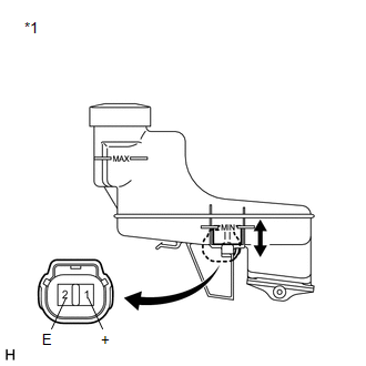
HINT:
A float is located inside the reservoir. Its position can be changed by increasing or decreasing the level of brake fluid.
Standard Resistance:
|
Tester Connection |
Switch Condition |
Specified Condition |
|---|---|---|
|
1 (+) - 2 (E) |
Switch OFF (Float up) |
1.9 to 2.1 kΩ |
|
1 (+) - 2 (E) |
Switch ON (Float down) |
Below 1 Ω |
|
*1 |
Component without harness connected (Brake Master Cylinder Reservoir (Brake Fluid Level Warning Switch)) |
HINT:
If there is no problem after finishing the above check, adjust the brake fluid level to the MAX level.
| NG | |
REPLACE BRAKE MASTER CYLINDER RESERVOIR ASSEMBLY (BRAKE FLUID LEVEL WARNING SWITCH) |
|
|
8. |
CHECK HARNESS AND CONNECTOR (COMBINATION METER - BRAKE FLUID LEVEL WARNING SWITCH) |
|
(a) Disconnect the combination meter connector. |
|
(b) Measure the resistance according to the value(s) in the table below.
Standard Resistance:
|
Tester Connection |
Condition |
Specified Condition |
|---|---|---|
|
E2-19 (B/LE) - A31-1 (+) |
Always |
Below 1 Ω |
|
E2-19 (B/LE) - Body ground |
Always |
10 kΩ or higher |
|
A31-2 (E) - Body ground |
Always |
Below 1 Ω |
|
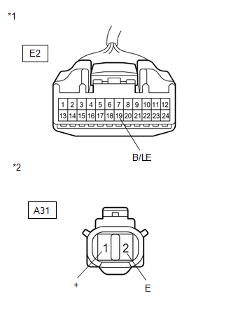
*1 |
Front view of wire harness connector (to Combination Meter) |
|
*2 |
Front view of wire harness connector (to Brake Master Cylinder Reservoir (Brake Fluid Level Warning Switch)) |
| NG | |
REPAIR OR REPLACE HARNESS OR CONNECTOR |
|
|
9. |
INSPECT COMBINATION METER ASSEMBLY |
(a) Disconnect the combination meter connector and the brake fluid level warning switch connector.
(b) Perform the Active Test of the combination meter (meter CPU) using the Techstream
(See page ).
(c) Check the combination meter.
OK:
The brake warning light turns on or off in accordance with the Techstream operation.
HINT:
If troubleshooting has been carried out according to Problem Symptoms Table,
refer back to the table and proceed to the next step before replacing the part (See
page ).
| OK | |
REPLACE BRAKE ACTUATOR ASSEMBLY |
| NG | |
REPLACE COMBINATION METER ASSEMBLY |
|
10. |
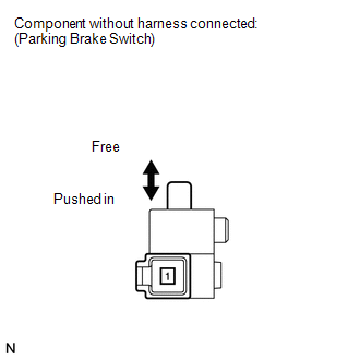
INSPECT PARKING BRAKE SWITCH |
|
(a) Turn the ignition switch off. |
|
(b) Disconnect the parking brake switch connector.
(c) Measure the resistance according to the value(s) in the table below.
Standard Resistance:
|
Tester Connection |
Switch Condition |
Specified Condition |
|---|---|---|
|
1 - Body ground |
Parking brake switch ON (Switch pin free) |
Below 1 Ω |
|
1 - Body ground |
Parking brake switch OFF (Switch pin pushed in) |
10 kΩ or higher |
| NG | |
REPLACE PARKING BRAKE SWITCH |
|
|
11. |
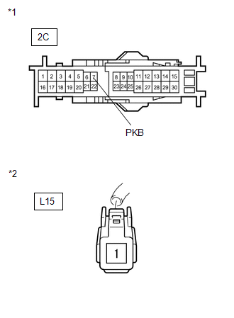
CHECK HARNESS AND CONNECTOR (MAIN BODY ECU - PARKING BRAKE SWITCH) |
|
(a) Disconnect the main body ECU connector. |
|
(b) Measure the resistance according to the value(s) in the table below.
Standard Resistance:
|
Tester Connection |
Condition |
Specified Condition |
|---|---|---|
|
2C-7 (PKB) - L15-1 |
Always |
Below 1 Ω |
|
2C-7 (PKB) - Body ground |
Always |
10 kΩ or higher |
|
*1 |
Front view of wire harness connector (to Main Body ECU (Driver Side Junction Block)) |
|
*2 |
Front view of wire harness connector (to Parking Brake Switch) |
HINT:
If troubleshooting has been carried out according to Problem Symptoms Table,
refer back to the table and proceed to the next step before replacing the part (See
page ).
| OK | |
REPLACE MAIN BODY ECU (DRIVER SIDE JUNCTION BLOCK) |
| NG | |
REPAIR OR REPLACE HARNESS OR CONNECTOR |
 ABS Warning Light does not Come ON
DESCRIPTION
The skid control ECU is connected to the combination meter via CAN communication.
WIRING DIAGRAM
Refer to ABS Warning Light Remains ON (See page
).
PROCEDURE
1.
...
 Brake Warning Light does not Come ON
DESCRIPTION
The skid control ECU is connected to the combination meter via CAN communication.
WIRING DIAGRAM
Refer to Brake Warning Light Remains ON (See page
).
PROCEDURE
1.
...
Other materials about Toyota Venza:
Reassembly
REASSEMBLY
PROCEDURE
1. INSTALL GENERATOR ROTOR ASSEMBLY
(a) Place the generator drive end frame on the generator pulley.
(b) Install the generator rotor to the generator drive end frame.
...
Installation
INSTALLATION
PROCEDURE
1. INSTALL SHIFT LEVER ASSEMBLY
NOTICE:
Check that the park/neutral position switch and the shift lever are in neutral.
(a) Slide the slider of the transmission control cable in the direction
indicated by the arrow an ...
Unlock Position Sensor Signal Circuit
DESCRIPTION
The unlock position sensor is one of the components comprising the steering lock
ECU (steering lock actuator assembly). The sensor switch contact closes when the
steering lock is released. The steering lock release signal is then sent to the
...

0.1587