Toyota Venza: Removal
REMOVAL
CAUTION / NOTICE / HINT
HINT:
Perform "Inspection After Repair" after replacing the fuel pump assembly (See
page .gif) ).
).
PROCEDURE
1. DISCHARGE FUEL SYSTEM PRESSURE
(a) Discharge fuel system pressure (See page
).
2. DISCONNECT CABLE FROM NEGATIVE BATTERY TERMINAL
NOTICE:
When disconnecting the cable, some systems need to be initialized after the cable
is reconnected (See page ).
3. REMOVE REAR SEAT ASSEMBLY LH
(a) Remove the rear seat assembly LH (See page
).
4. REMOVE REAR SEAT ASSEMBLY RH
(a) Remove the rear seat assembly RH (See page
).
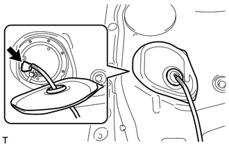
5. REMOVE REAR FLOOR SERVICE HOLE COVER
(a) Turn over the rear floor carpet and the rear floor silencer.
|
(b) Remove the service hole cover and disconnect the fuel pump connector. |
|
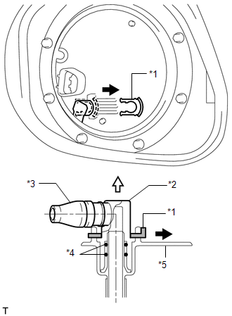
6. REMOVE FUEL SUCTION TUBE ASSEMBLY WITH PUMP AND GAUGE
|
(a) Remove the tube joint clip, and pull out the fuel pump tube. Text in Illustration
NOTICE:
|
|
|
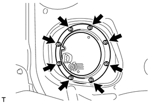
(b) Remove the 8 bolts and the fuel tank vent tube set plate. HINT: While holding the fuel suction tube by hand, remove the fuel tank vent tube set plate. |
|
|
(c) Disconnect the clip and fuel tube. |
|
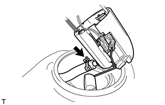
(d) Remove the fuel suction tube assembly with pump and gauge from the fuel tank.
NOTICE:
- Make sure that the sender gauge arm does not bend.
- Do not damage the fuel suction tube.
(e) Remove the fuel suction tube set gasket from the fuel tank.
 Components
COMPONENTS
ILLUSTRATION
ILLUSTRATION
ILLUSTRATION
ILLUSTRATION
...
 Disassembly
DISASSEMBLY
PROCEDURE
1. REMOVE FUEL SENDER GAUGE
2. SEPARATE FUEL SUCTION PLATE SUB-ASSEMBLY
(a) Disconnect the fuel pump connector from the fuel suction plate.
NOTICE:
Do not ...
Other materials about Toyota Venza:
Test Mode Procedure
TEST MODE PROCEDURE
1. ENTER TEST MODE (SIGNAL CHECK MODE)
(a) Turn the ignition switch off.
(b) Connect the Techstream to the DLC3.
(c) Turn the ignition switch to ON.
(d) Check that the tire pressure warning light comes on for 3 seconds and then
goes ...
Front Door Speaker
Components
COMPONENTS
ILLUSTRATION
Removal
REMOVAL
PROCEDURE
1. DISCONNECT CABLE FROM NEGATIVE BATTERY TERMINAL
CAUTION:
Wait at least 90 seconds after disconnecting the cable from the negative (-)
battery terminal to disable the SRS system (Se ...
Installation
INSTALLATION
PROCEDURE
1. INSTALL POWER DISTRIBUTION
(a) Connect the 3 connectors.
(b) Engage the 2 claws to temporarily install the power distribution
as shown in the illustration.
...

0.1466