Toyota Venza: Disassembly
DISASSEMBLY
PROCEDURE
1. REMOVE TAIL AND STOP LIGHT BULB
|
(a) Turn the tail and stop light bulb and the rear combination light socket and wire in the direction indicated by the arrow shown in the illustration, and remove them as a unit. |
|
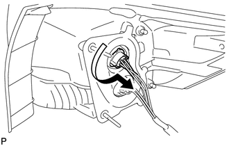
(b) Remove the tail and stop light bulb from the rear combination light socket and wire.
2. REMOVE REAR TURN SIGNAL LIGHT BULB
|
(a) Turn the rear turn signal light bulb and rear combination light socket and wire in the direction indicated by the arrow shown in the illustration, and remove them as a unit. |
|
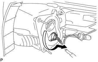
(b) Remove the rear turn signal light bulb from the rear combination light socket and wire.
3. REMOVE REAR BUMPER UPPER RETAINER
|
(a) Remove the 2 screws. |
|
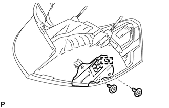
(b) Disengage the guide and remove the rear bumper upper retainer.
 Removal
REMOVAL
PROCEDURE
1. REMOVE REAR DOOR SCUFF PLATE
2. DISCONNECT REAR DOOR OPENING TRIM WEATHERSTRIP
3. REMOVE TONNEAU COVER ASSEMBLY (w/ Tonneau Cover)
4. REMOVE DECK BOARD ASSEMBLY
...
 Reassembly
REASSEMBLY
PROCEDURE
1. INSTALL REAR BUMPER UPPER RETAINER
(a) Engage the guide.
(b) Install the rear bumper upper retainer with the 2 scr ...
Other materials about Toyota Venza:
Engine Coolant Temperature Receiver Gauge Malfunction
DESCRIPTION
In this circuit, the meter CPU receives engine coolant temperature signals from
the ECM using the CAN communication system (CAN No. 1 Bus). The meter CPU displays
engine coolant temperature that is calculated based on the data received from th ...
Installation
INSTALLATION
PROCEDURE
1. TEMPORARILY INSTALL REAR NO. 1 SUSPENSION ARM ASSEMBLY LH
(a) Temporarily install the rear No. 1 suspension arm assembly LH to
the rear suspension member with the bolt (B).
Text in Illustration
...
If the battery is discharged
The following procedures may be used to start the engine if the battery is
discharged.
You can call your Toyota dealer or qualified repair shop.
If you have a set of jumper (or booster) cables and a second vehicle with a 12
volt battery, you can jump sta ...

0.182