
Toyota Venza: Reassembly
REASSEMBLY
PROCEDURE
1. INSTALL REAR BUMPER UPPER RETAINER
|
(a) Engage the guide. |
|
.png)
(b) Install the rear bumper upper retainer with the 2 screws.
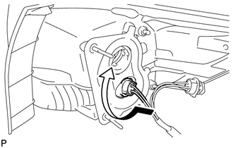
2. INSTALL REAR TURN SIGNAL LIGHT BULB
(a) Install the rear turn signal light bulb to the rear combination light socket and wire.
|
(b) Turn the rear turn signal light bulb and rear combination light socket and wire in the direction indicated by the arrow shown in the illustration to install them as a unit. |
|
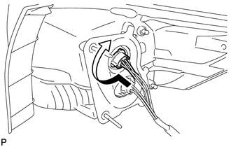
3. INSTALL TAIL AND STOP LIGHT BULB
(a) Install the tail and stop light bulb to the rear combination light socket and wire.
|
(b) Turn the tail and stop light bulb and the rear combination light socket and wire in the direction indicated by the arrow shown in the illustration to install them as a unit. |
|
 Disassembly
DISASSEMBLY
PROCEDURE
1. REMOVE TAIL AND STOP LIGHT BULB
(a) Turn the tail and stop light bulb and the rear combination light
socket and wire in the direction indicated by the arrow ...
 Installation
INSTALLATION
PROCEDURE
1. INSTALL REAR COMBINATION LIGHT ASSEMBLY
(a) Engage the guide and 2 pins, and install the rear combination light
assembly as shown in the illustration.
Te ...
Other materials about Toyota Venza:
Removal
REMOVAL
PROCEDURE
1. PRECAUTION (w/ Navigation System)
NOTICE:
After turning the ignition switch off, waiting time may be required before disconnecting
the cable from the negative (-) battery terminal. Therefore, make sure to read the
disconnecting the ...
Inspection
INSPECTION
PROCEDURE
1. INSPECT WINDSHIELD WIPER SWITCH ASSEMBLY
(a) Measure the resistance according to the value(s) in the table below.
Standard Resistance:
Front Wiper Switch
Tester Connection
Switch ...
Problem Symptoms Table
PROBLEM SYMPTOMS TABLE
HINT:
Use the table below to help determine the cause of problem symptoms.
If multiple suspected areas are listed, the potential causes of the symptoms
are listed in order of probability in the "Suspected Area" ...

0.1451