Toyota Venza: Initialization
INITIALIZATION
HINT:
In vehicles equipped with the push-button start function, the starting function may not be operational after recharging or while jump-starting a discharged battery. This condition is most likely to occur if battery voltage drops below 9 V. The following procedure has been developed to address this condition.
1. INITIALIZATION PROCEDURE
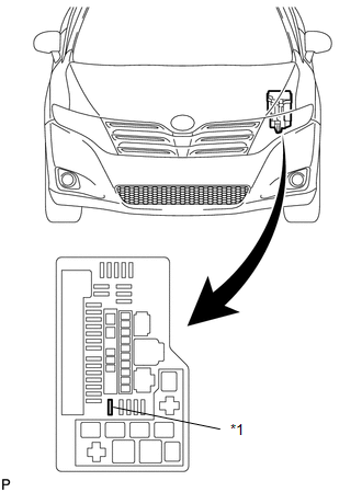
(a) Confirm that the D/C CUT fuse is installed.
 Text in Illustration
|
*1 |
DCC Fuse |
HINT:
If the D/C CUT fuse is not installed, install it at this time.
(b) Move the shift lever to P.
(c) Turn the engine switch off.
(d) Open the driver's door.
HINT:
Opening the driver's door will start an initialization process between the steering lock ECU (steering lock actuator assembly) and the engine room junction block.
(e) Depress the brake pedal.
(f) Press the engine switch.
 How To Proceed With Troubleshooting
CAUTION / NOTICE / HINT
HINT:
Perform troubleshooting in accordance with the following flowchart.
*: Use the Techstream.
PROCEDURE
1.
VEHICLE BROUGHT TO ...
 Problem Symptoms Table
PROBLEM SYMPTOMS TABLE
HINT:
Use the table below to help determine the cause of problem symptoms.
If multiple suspected areas are listed, the potential causes of the symptoms
are lis ...
Other materials about Toyota Venza:
P/W Master Switch Communication Stop (B1206)
DESCRIPTION
This DTC is stored when LIN communication between the multiplex network master
switch assembly and main body ECU (driver side junction block assembly) stops for
more than 10 seconds.
DTC No.
DTC Detection Condition
...
Transmission Fluid Temperature Sensor "A" Performance (P0711)
DESCRIPTION
The Automatic Transmission Fluid (ATF) temperature sensor converts the fluid
temperature into a resistance value for use by the TCM.
The TCM applies a voltage to the temperature sensor through terminal THO1 of
the TCM.
The sensor resistance ...
Customize Parameters
CUSTOMIZE PARAMETERS
PROCEDURE
1. CUSTOMIZE INTUITIVE PARKING ASSIST SYSTEM
(a) Customizing with the Techstream
NOTICE:
When the customer requests a change in a function, first make sure that
the function can be customized.
Be sure to make ...

0.7309