Toyota Venza: Inspection
INSPECTION
PROCEDURE
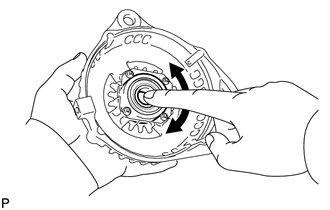
1. INSPECT GENERATOR PULLEY WITH CLUTCH
|
(a) Hold the center of the pulley, and confirm that the outer ring turns counterclockwise and does not turn clockwise. Text in Illustration
If the result is not as specified, replace the generator pulley with clutch. |
|

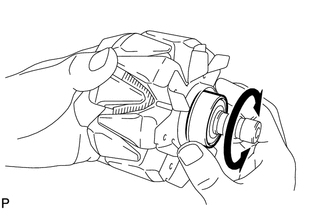
2. INSPECT GENERATOR DRIVE END FRAME BEARING
|
(a) Check that the bearing is not rough or worn and that it rotates smoothly. OK: The bearing rotates smoothly. If the bearing does not rotate smoothly, replace the bearing. |
|
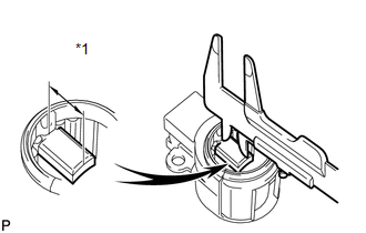
3. INSPECT GENERATOR BRUSH HOLDER ASSEMBLY
|
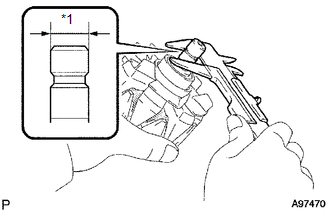
(a) Using a vernier caliper, measure the brush length. Text in Illustration
Standard length: 9.5 to 11.5 mm (0.374 to 0.453 in.) Minimum length: 4.5 mm (0.177 in.) If the brush length is less than the minimum, replace the generator brush holder assembly. |
|
4. INSPECT GENERATOR ROTOR ASSEMBLY
|
(a) Check that the generator rotor bearing is not rough or worn. If the result is not as specified, replace the generator rotor assembly. |
|
|
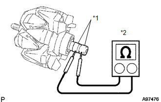
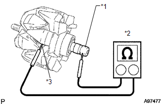
(b) Check the rotor for an open circuit. Text in Illustration
(1) Measure the resistance according to the value(s) in the table below. Standard Resistance:
If the result is not as specified, replace the generator rotor assembly. |
|
|
(c) Check if the rotor is grounded. Text in Illustration
(1) Measure the resistance according to the value(s) in the table below. Standard Resistance:
If the result is not as specified, replace the generator rotor assembly. |
|
(d) Check the slip ring diameter.
|
(1) Using a vernier caliper, measure the diameter of each slip ring. Text in Illustration
Standard diameter: 14.2 to 14.4 mm (0.559 to 0.567 in.) Minimum diameter: 14 mm (0.551 in.) If the diameter is less than the minimum, replace the generator rotor assembly. |
|
 Disassembly
DISASSEMBLY
PROCEDURE
1. REMOVE GENERATOR PULLEY CAP
(a) Using a screwdriver, puncture the center of the generator pulley
cap and pry it off.
NOTICE:
Do not reuse the generator ...
 Reassembly
REASSEMBLY
PROCEDURE
1. INSTALL GENERATOR ROTOR ASSEMBLY
(a) Place the generator drive end frame on the generator pulley.
(b) Install the ...
Other materials about Toyota Venza:
Problem Symptoms Table
PROBLEM SYMPTOMS TABLE
HINT:
Use the table below to help determine the cause of problem symptoms.
If multiple suspected areas are listed, the potential causes of the symptom
are listed in order of probability in the "Suspected Area" ...
Inspection
INSPECTION
PROCEDURE
1. INSPECT PARK/NEUTRAL POSITION SWITCH ASSEMBLY
(a) Measure the resistance according to the value(s) in the table below
when the shift lever is moved to each position.
Text in Illustration
*1
...
Check Mode Procedure
CHECK MODE PROCEDURE
HINT:
Techstream only:
Compared to normal mode, check mode is more sensitive to malfunctions. Therefore,
check mode can detect malfunctions that cannot be detected in normal mode.
NOTICE:
All the stored DTCs and freeze frame data ar ...

0.1147