Toyota Venza: Diagnosis System
DIAGNOSIS SYSTEM
1. DESCRIPTION
(a) When troubleshooting On-Board Diagnostic (OBD II) vehicles, the vehicle must be connected to the OBD II scan tool (complying with SAE J1987). Various data output from the vehicle TCM can then be read.
(b) OBD II regulations require that the vehicle on-board computer illuminate the Malfunction Indicator Lamp (MIL) on the instrument panel when the computer detects a malfunction in:

(1) The emission control system/components
(2) The powertrain control components (which affect vehicle emissions)
(3) The computer
In addition, the applicable Diagnostic Trouble Codes (DTCs) prescribed by SAE J2012 are recorded in the TCM memory.
When a malfunction does not reoccur, the MIL stays illuminated until the ignition switch is turned off, and the MIL turns off when the engine is started. However, the DTCs will remain recorded in the TCM memory.
(c) To check DTCs, connect the Techstream to the Data Link Connector 3 (DLC3) of the vehicle. The Techstream displays DTCs, freeze frame data and a variety of engine data.
The DTCs and freeze frame data can be cleared with the Techstream (See page
.gif) ).
).
2. NORMAL MODE AND CHECK MODE
(a) The diagnosis system operates in "normal mode" during normal vehicle use. In normal mode, "2 trip detection logic" is used to ensure accurate detection of malfunctions. "Check mode" is also available to technicians as an option. In check mode, "1 trip detection logic" is used for simulating malfunction symptoms and increasing the system's ability to detect malfunctions, including intermittent malfunctions.
3. 2 TRIP DETECTION LOGIC
(a) When a malfunction is first detected, the malfunction is temporarily stored in the TCM memory (1st trip). If the same malfunction is detected during the next drive cycle, the MIL is illuminated (2nd trip).
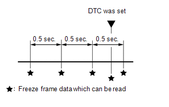
4. FREEZE FRAME DATA
(a) The ECM records vehicle and driving condition information as freeze frame data the moment a DTC is stored. When troubleshooting, freeze frame data can be helpful in determining whether the vehicle was running or stopped, whether the engine was warmed up or not, whether the air/fuel ratio was lean or rich, as well as other data recorded at the time of a malfunction.
(b) The Techstream records freeze frame data in 5 different instances: 1) 3 times before the DTC is set, 2) once when the DTC is set, and 3) once after the DTC is set. These sets of data can be used to simulate the vehicle condition around the time when the malfunction occurred. The data may help in finding the cause of the malfunction, or in judging if the DTC was caused by a temporary malfunction.
5. CHECK DATA LINK CONNECTOR 3 (DLC3)
(a) Check the DLC3 (See page )
6. CHECK MIL
(a) Check that the MIL illuminates when turning the ignition switch to ON.
If the MIL does not illuminate, there is a problem in the MIL circuit (See page
).
(b) When the engine is started, the MIL should turn off.
 Problem Symptoms Table
PROBLEM SYMPTOMS TABLE
HINT:
Use the table below to help determine the cause of problem symptoms.
If multiple suspected areas are listed, the potential causes of the symptoms
are lis ...
 Terminals Of Ecu
TERMINALS OF ECU
1. TCM
HINT:
Each TCM terminal standard voltage is shown in the table below.
In the table, first follow the information under "Condition". Look under "Terminal
...
Other materials about Toyota Venza:
Removal
REMOVAL
PROCEDURE
1. RECOVER REFRIGERANT FROM REFRIGERATION SYSTEM
2. DISCONNECT CABLE FROM NEGATIVE BATTERY TERMINAL
NOTICE:
When disconnecting the cable, some systems need to be initialized after the cable
is reconnected (See page ).
3. REMOVE FR ...
Reassembly
REASSEMBLY
PROCEDURE
1. INSTALL NO. 2 STEERING RACK BOOT
(a) Apply lithium soap base glycol grease to the inside of the small
opening of a new No. 2 steering rack boot.
(b) Install the No. 2 ste ...
Disassembly
DISASSEMBLY
PROCEDURE
1. REMOVE SEAT ADJUSTER COVER CAP
(a) Remove the seat adjuster cover cap.
HINT:
Use the same procedure for the RH side and LH side.
2. REMOVE RECLINING POWER SEAT SWITCH ...

0.1915