Toyota Venza: Installation
INSTALLATION
PROCEDURE
1. INSTALL BRAKE ACTUATOR ASSEMBLY
|
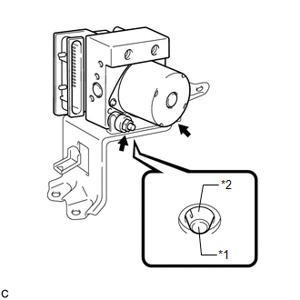
(a) Install the brake actuator assembly to the brake actuator bracket assembly with the 2 nuts. Torque: 8.0 N·m {82 kgf·cm, 71 in·lbf} NOTICE:
|
|
2. INSTALL BRAKE ACTUATOR WITH BRACKET
|
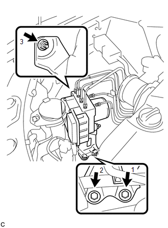
(a) Install the brake actuator with bracket to the body with the nut and 2 bolts. Torque: 19 N·m {194 kgf·cm, 14 ft·lbf} NOTICE:
|
|
|
(b) Connect the brake actuator connector. NOTICE:
|
|
|
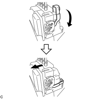
(c) Temporarily tighten each brake line to the correct positions of the brake actuator with bracket as shown in the illustration. Text in Illustration
|
|
.png)
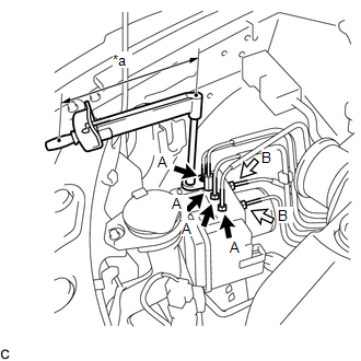
(d) Using a union nut wrench, fully tighten 4 brake lines (A).
 Text in Illustration
|
*a |
Torque Wrench Fulcrum Length |
 |
Flare Nut A (10 mm) |
.png) |
Flare Nut B (12 mm) |
Torque:
Specified Tightening Torque :
15 N·m {155 kgf·cm, 11 ft·lbf}
HINT:
- Calculate the torque wrench reading when changing the fulcrum length
for the torque wrench (See page
.gif) ).
).
- When using a union nut wrench (fulcrum length of 22 mm (0.866 in.))
+ torque wrench (fulcrum length of 250 mm (9.84 in.)):
14 N*m (142 kgf*cm, 10 ft.*lbf)
(e) Using a union nut wrench, fully tighten 2 brake lines (B).
Torque:
Specified Tightening Torque :
20 N·m {199 kgf·cm, 14 ft·lbf}
HINT:
- Calculate the torque wrench reading when changing the fulcrum length
for the torque wrench (See page ).
- When using a union nut wrench (fulcrum length of 20 mm (0.787 in.))
+ torque wrench (fulcrum length of 250 mm (9.84 in.)):
18 N*m (184 kgf*cm, 13 ft.*lbf)
|
(f) Install the clamp of the suction hose sub-assembly to the brake actuator bracket assembly. |
|
.png)
3. INSTALL RADIATOR RESERVE TANK ASSEMBLY
|
(a) Install the radiator reserve tank assembly. |
|
.png)
(b) Install the radiator reserve tank cap assembly.
4. FILL RESERVOIR WITH BRAKE FLUID
5. BLEED BRAKE MASTER CYLINDER
6. BLEED BRAKE LINE
7. INSPECT FLUID LEVEL IN RESERVOIR
8. INSPECT FOR BRAKE FLUID LEAK
9. CONNECT CABLE TO NEGATIVE BATTERY TERMINAL
NOTICE:
When disconnecting the cable, some systems need to be initialized after the cable
is reconnected (See page ).
10. PERFORM ENGINE VARIANT LEARNING
(See page )
11. INSPECT BRAKE ACTUATOR USING TECHSTREAM
(See page )
 Removal
REMOVAL
PROCEDURE
1. DISCONNECT CABLE FROM NEGATIVE BATTERY TERMINAL
NOTICE:
When disconnecting the cable, some systems need to be initialized after the cable
is reconnected (See page ).
2. RE ...
 Brake Pedal Load Sensing Switch
On-vehicle Inspection
ON-VEHICLE INSPECTION
PROCEDURE
1. INSPECT BRAKE PEDAL LOAD SENSING SWITCH
NOTICE:
Do not remove the brake pedal load sensing switch from the brake pedal
suppo ...
Other materials about Toyota Venza:
Ambient Temperature Sensor
Components
COMPONENTS
ILLUSTRATION
Inspection
INSPECTION
PROCEDURE
1. INSPECT AMBIENT TEMPERATURE SENSOR
(a) Measure the resistance according to the value(s) in the table below.
Standard Resistance:
Tester Connection
C ...
Replacement
REPLACEMENT
PROCEDURE
1. RECOVER REFRIGERANT FROM REFRIGERATION SYSTEM
(a) Start up the engine.
(b) Turn the A/C switch on.
(c) Operate the cooler compressor at an engine speed of approximately 1000 rpm
for 5 to 6 minutes to circulate the refrigerant. T ...
Door Control Switch
Components
COMPONENTS
ILLUSTRATION
Inspection
INSPECTION
PROCEDURE
1. INSPECT DOOR CONTROL SWITCH ASSEMBLY
(a) Measure the resistance according to the value(s) in the table below.
Standard Resistance:
Tester Conn ...

0.114