Toyota Venza: Diagnosis System
DIAGNOSIS SYSTEM
1. DESCRIPTION
(a) Diagnostic System
When troubleshooting a vehicle with a diagnostic system, the only difference from the usual troubleshooting procedure is connecting the Techstream to the vehicle and reading various data output from the vehicle steering lock ECU (steering lock actuator assembly).
The steering lock ECU (steering lock actuator assembly) records DTCs when the computer detects a malfunction in the computer itself or in its circuits.
To check the DTCs, connect the Techstream to the DLC3 on the vehicle. The Techstream enables the DTCs to be cleared, the indicators to be activated, and the Data List to be checked.
(b) The diagnosis information of the steering lock ECU (steering lock actuator assembly) is transmitted to the Techstream via the certification ECU (smart key ECU assembly) as the steering lock ECU (steering lock actuator assembly) is not connected to CAN.
(c) Check the DLC3.
(1) Check the DLC3 (See page .gif) ).
).
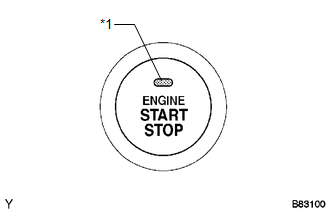
2. WARNING FUNCTION OF ENGINE SWITCH INDICATOR
(a) The steering lock ECU (steering lock actuator assembly) blinks the LED indicator of the engine switch when any of the following problems occurs in the system:
 Text in Illustration
|
*1 |
Indicator Light |
|
Detection Item |
Indicator Light Blink Pattern |
Indication Status |
Countermeasure |
|---|---|---|---|
|
Steering lock is still not released |
|
The motor operates to release the steering lock, but the steering lock cannot be released (e.g. the lock bar is stuck in the steering column). |
Push the engine switch while turning the steering wheel left or right. |
|
Malfunction in push-button start system |
|
|
Troubleshoot by following "How to Proceed with Troubleshooting" (See
page |
 Terminals Of Ecu
TERMINALS OF ECU
1. STEERING LOCK ECU (STEERING LOCK ACTUATOR ASSEMBLY)
Terminal No. (Symbol)
Wiring Color
Terminal Description
Condition
Spe ...
 Dtc Check / Clear
DTC CHECK / CLEAR
1. CHECK DTCS
(a) Turn the engine switch off.
(b) Connect the Techstream to the DLC3.
(c) Turn the engine switch on (IG).
(d) Turn the Techstream on.
(e) Check for DTCs. Enter ...
Other materials about Toyota Venza:
Terminals Of Ecu
TERMINALS OF ECU
1. REAR TELEVISION CAMERA ASSEMBLY
(a) Disconnect the R21 rear television camera assembly connector.
(b) Measure the voltage on the wire harness side connector according to the value(s)
in the table below.
Terminal No. (Symb ...
System Description
SYSTEM DESCRIPTION
1. AUTOMATIC LIGHT CONTROL SYSTEM
When the light control switch is in the AUTO position, the automatic light control
system detects ambient light levels and controls the low beam headlights, parking
lights, taillights, marker lights an ...
Problem Symptoms Table
PROBLEM SYMPTOMS TABLE
HINT:
Use the table below to help determine the cause of problem symptoms.
If multiple suspected areas are listed, the potential causes of the symptoms
are listed in order of probability in the "Suspected Area" ...

0.1555