Toyota Venza: Components
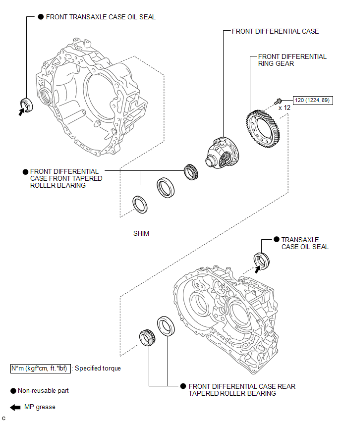
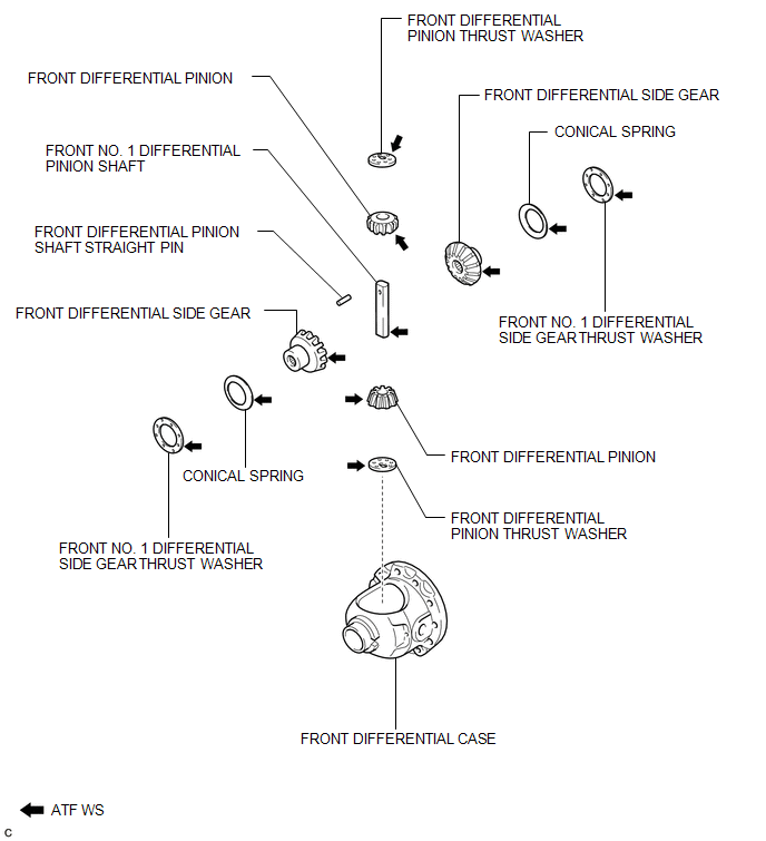
COMPONENTS
ILLUSTRATION
ILLUSTRATION

 Disassembly
DISASSEMBLY
PROCEDURE
1. REMOVE FRONT TRANSAXLE CASE OIL SEAL
(a) Using SST, remove the front transaxle case oil seal from the transaxle
housing.
SST: 09308-00010
...
Other materials about Toyota Venza:
Removal
REMOVAL
PROCEDURE
1. REMOVE ENGINE ASSEMBLY WITH TRANSAXLE (for 2GR-FE)
HINT:
Refer to the procedure up to Remove Engine Assembly with Transaxle (See page
).
2. REMOVE ENGINE ASSEMBLY WITH TRANSAXLE (for 1AR-FE)
HINT:
Refer to the procedure up to Remo ...
No Sound can be Heard from Speakers
PROCEDURE
1.
CHECK AUDIO SETTINGS
(a) In sound setting mode, set volume, fader and balance to the initial values
and check that the sound is normal.
OK:
Audio system returns to normal.
HINT:
Sound quality adjustment mea ...
Removal
REMOVAL
PROCEDURE
1. REMOVE YAW RATE AND ACCELERATION SENSOR
HINT:
Refer to the instructions for Removal of the yaw rate and acceleration sensor
(See page ).
2. REMOVE REAR NO. 2 AIR DUCT
3. REMOVE REAR NO. 1 AIR DUCT
4. REMOVE FRONT NO. 2 FLOO ...

0.1249