Toyota Venza: Components
COMPONENTS
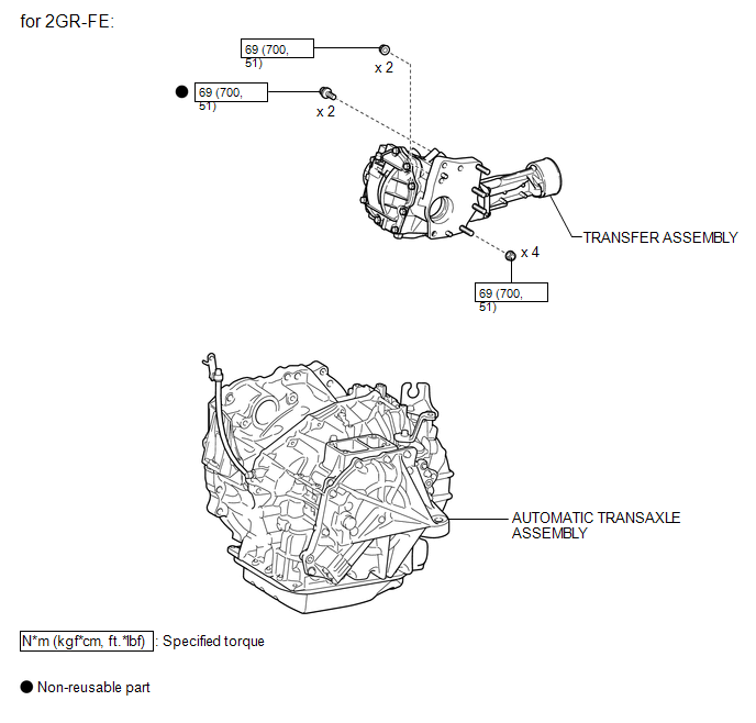
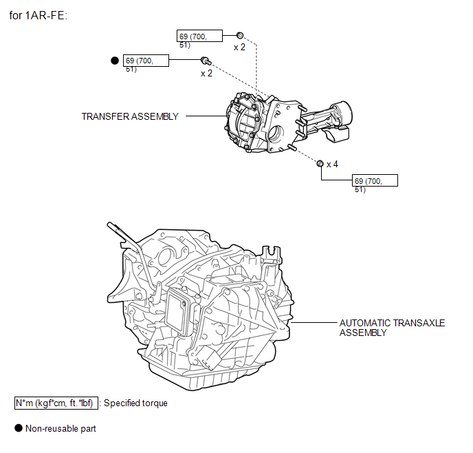
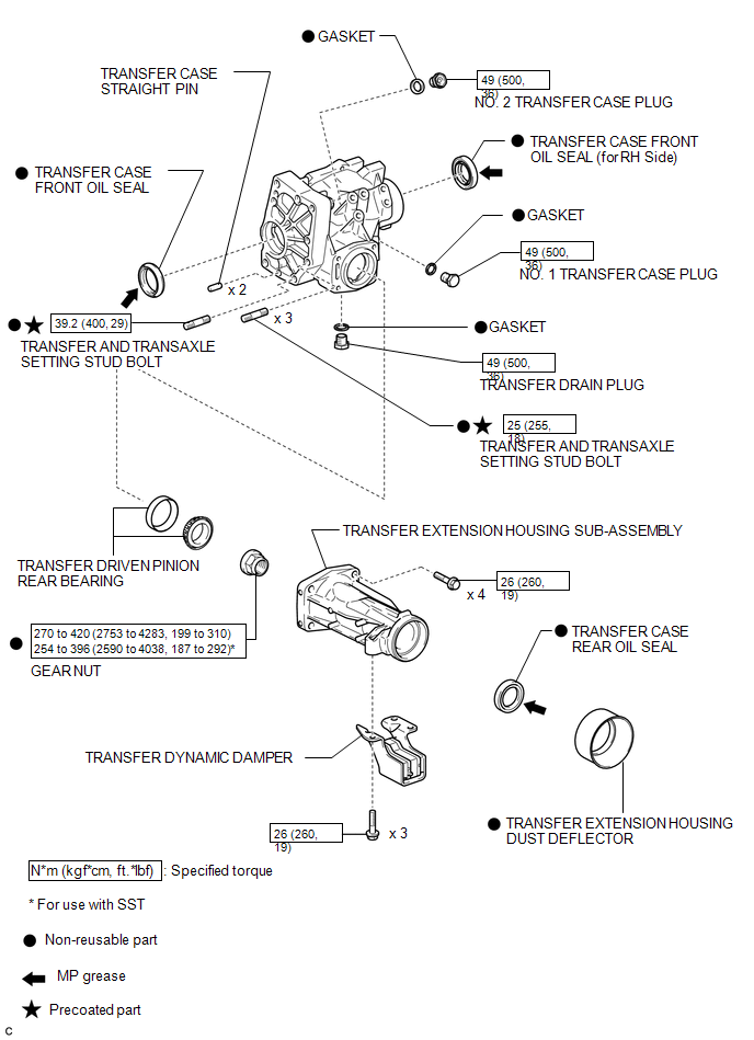
ILLUSTRATION
ILLUSTRATION
ILLUSTRATION
ILLUSTRATION
.png)

 Removal
REMOVAL
PROCEDURE
1. REMOVE AUTOMATIC TRANSAXLE ASSEMBLY (for 2GR-FE)
See page
2. REMOVE AUTOMATIC TRANSAXLE ASSEMBLY (for 1AR-FE)
See page
3. REMOVE TRANSFER ASSEMBLY
(a) Remove ...
Other materials about Toyota Venza:
Engine Immobiliser System Malfunction (B2799)
DESCRIPTION
This DTC is stored when one of the following occurs: 1) the ECM detects errors
in its own communications with the transponder key ECU assembly; 2) the ECM detects
errors in the communication lines; or 3) the ECU communication ID between the tr ...
Inspection
INSPECTION
PROCEDURE
1. INSPECT PAD LINING THICKNESS
(a) Using a ruler, measure the pad lining thickness.
Text in Illustration
*1
Ruler
Standard thickness of a new pad:
12.0 mm (0.472 ...
Installation
INSTALLATION
PROCEDURE
1. INSTALL CHARCOAL CANISTER LEAK DETECTION PUMP SUB-ASSEMBLY
(a) Engage the 2 claws to install a new charcoal canister leak detection
pump sub-assembly to the charcoal canister assembly.
NOTICE:
Do n ...

0.1322