Toyota Venza: Personal Light
Components
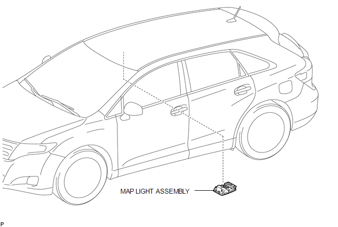
COMPONENTS
ILLUSTRATION
Removal
REMOVAL
PROCEDURE
1. REMOVE MAP LIGHT ASSEMBLY
|
(a) Using a moulding remover, disengage the 2 claws and 2 clips. Text in Illustration
|
|
.png)
(b) Disengage the fastener.
(c) Disconnect each connector and remove the map light assembly.
Installation
INSTALLATION
PROCEDURE
1. INSTALL MAP LIGHT ASSEMBLY
(a) Connect each connector.
|
(b) Engage the fastener. Text in Illustration
|
|
.png)
(c) Engage the 2 claws and 2 clips, and install the map light assembly.
 Luggage Compartment Room Light
Components
COMPONENTS
ILLUSTRATION
Removal
REMOVAL
PROCEDURE
1. REMOVE NO. 2 ROOM LIGHT ASSEMBLY
(a) Using a moulding remover, disengage the claw.
...

Other materials about Toyota Venza:
System Description
SYSTEM DESCRIPTION
1. POWER BACK DOOR SYSTEM DESCRIPTION
(a) The power back door system controls the power back door by automatically
opening and closing the power back door with a motor.
(1) The power back door system operates only when the necessary con ...
Correct driving posture
Drive with a good posture as follows:
1. Sit upright and well back in the seat.
2. Adjust the position of the seat forward or backward to ensure the pedals can
be reached and easily depressed to the extent required. 3. Adjust the seatback so
that the c ...
Precaution
PRECAUTION
NOTICE:
When disconnecting the cable from the negative (-) battery terminal, initialize
the following systems after the cable is reconnected.
System Name
See Procedure
Back Door Closer System
...

0.1723