Toyota Venza: Components
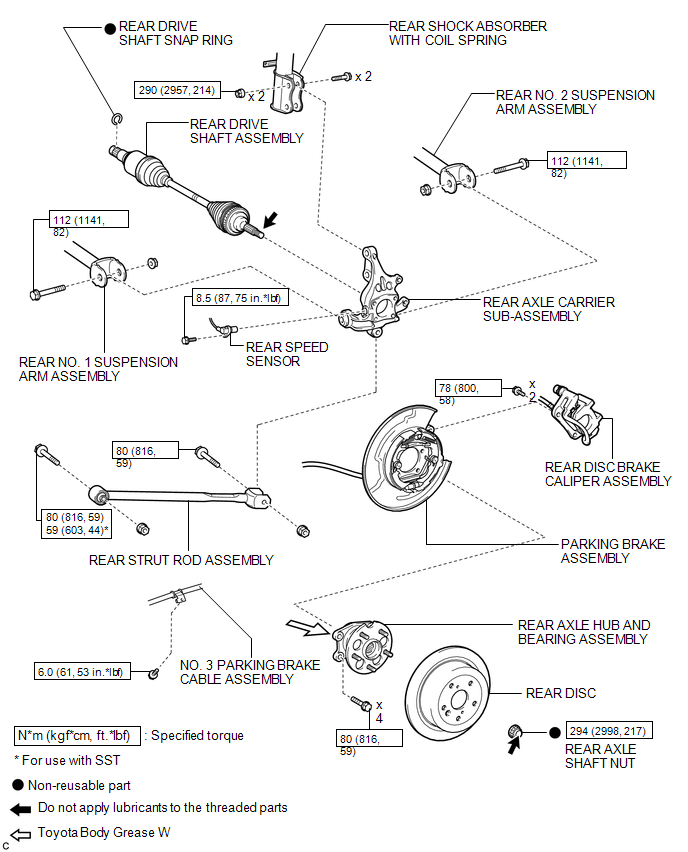
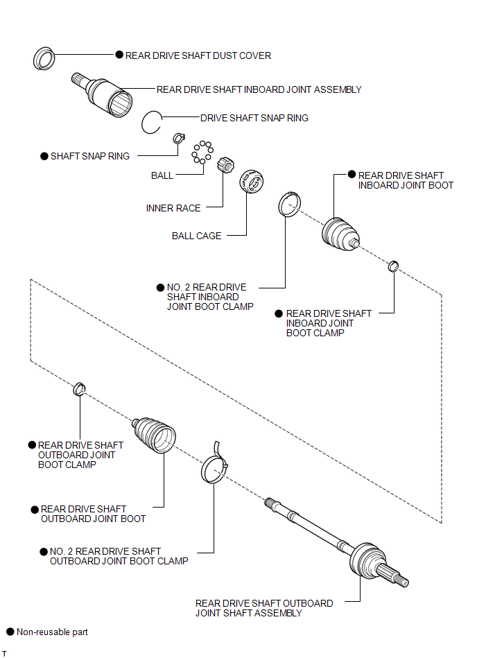
COMPONENTS
ILLUSTRATION
ILLUSTRATION

 Removal
REMOVAL
CAUTION / NOTICE / HINT
HINT:
Use the same procedure for the LH side and RH side.
The following procedure listed below is for the LH side.
PROCEDURE
1. REMOVE REAR WHEEL ...
Other materials about Toyota Venza:
Removal
REMOVAL
PROCEDURE
1. REMOVE FRONT DOOR SCUFF PLATE LH
2. REMOVE COWL SIDE TRIM SUB-ASSEMBLY LH
3. REMOVE LOWER NO. 1 INSTRUMENT PANEL FINISH PANEL
4. REMOVE OUTER MIRROR SWITCH ASSEMBLY
(a) Disengage the 2 claws and remove the outer m ...
Data Signal Circuit between Radio Receiver and Extension Module
DESCRIPTION
The stereo component tuner assembly sends the image data signal to the radio
and display receiver assembly via this circuit.
WIRING DIAGRAM
PROCEDURE
1.
CHECK NAVIGATION WIRE
(a) Remove the navigation wire ( ...
All Doors LOCK/UNLOCK Functions do not Operate Via Door Control Switch
DESCRIPTION
The main body ECU (driver side junction block assembly) receives switch signals
from the door control switch and activates the door lock motor on each door according
to these signals.
WIRING DIAGRAM
PROCEDURE
1.
REA ...

0.1549