
Toyota Venza: Components
COMPONENTS
ILLUSTRATION
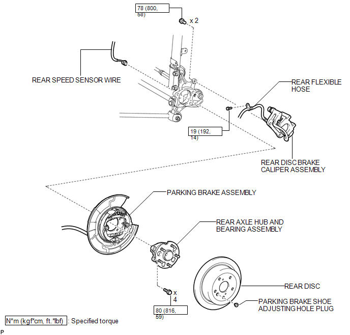

 On-vehicle Inspection
ON-VEHICLE INSPECTION
CAUTION / NOTICE / HINT
HINT:
Use the same procedure for the RH side and LH side.
The procedure listed below is for the LH side.
PROCEDURE
1. REMOVE REAR W ...
Other materials about Toyota Venza:
Installation
INSTALLATION
PROCEDURE
1. INSTALL STUD BOLT (for LH Side)
(a) Using SST and a socket wrench (21 mm), install the stud bolt.
Text in Illustration
*1
Socket Wrench
*2
...
Installation
INSTALLATION
PROCEDURE
1. INSTALL STEREO COMPONENT TUNER ASSEMBLY
2. INSTALL NAVIGATION WIRE
(a) Connect the 3 connectors to install the navigation wire.
3. INSTALL STEREO COMPONENT TUNER ASSEMBLY WITH WIRE
(a) Install the stereo component tuner assembly ...
Installation
INSTALLATION
PROCEDURE
1. INSTALL BRAKE PEDAL SUPPORT ASSEMBLY
(a) Install the brake pedal support assembly to the instrument panel
reinforcement with the bolt.
Torque:
19 N·m {195 kgf·cm, 14 ft·lbf}
...

0.1512