Toyota Venza: Components
COMPONENTS
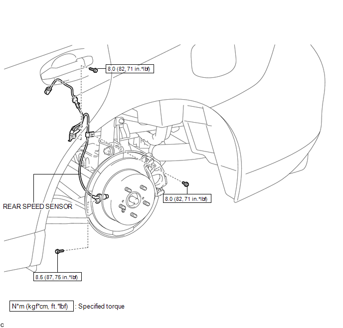
ILLUSTRATION
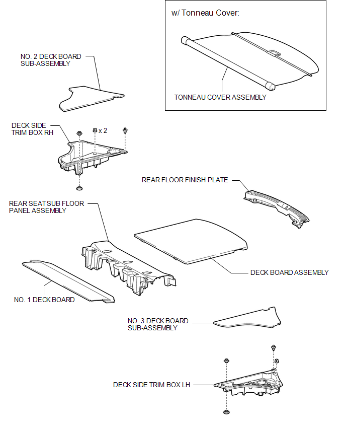
ILLUSTRATION
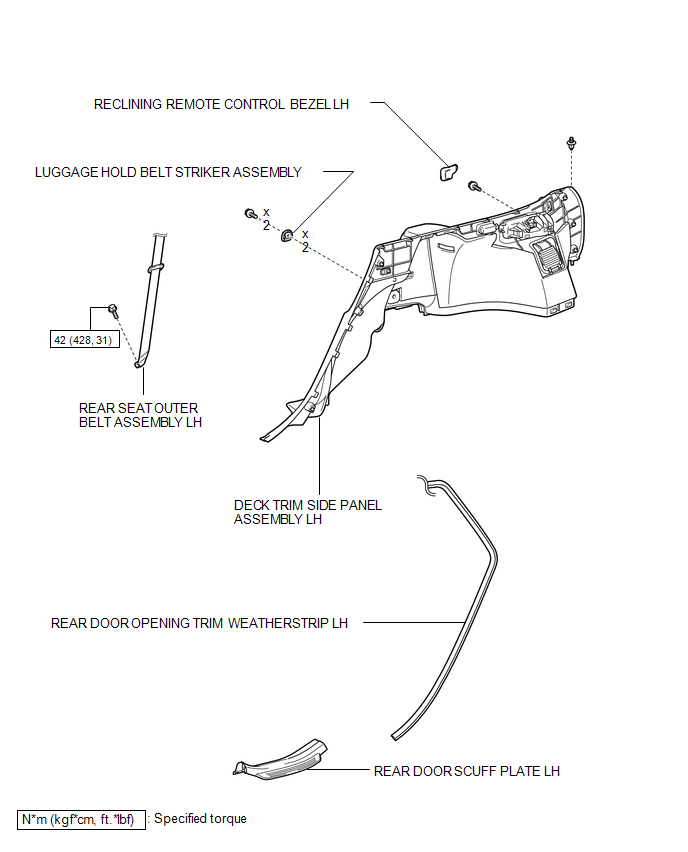
ILLUSTRATION

 Installation
INSTALLATION
CAUTION / NOTICE / HINT
HINT:
Use the same procedure for the LH side and RH side.
The following procedure is for the LH side.
If the sensor rotor needs to be replaced, ...
Other materials about Toyota Venza:
Engine Speed Signal Error (Test Mode DTC) (C2194/94)
DESCRIPTION
The tire pressure warning ECU receives an engine speed signal from the ECM. This
DTC is stored upon entering signal check mode (test mode), and cleared when an engine
speed signal of 1000 rpm is detected for 3 seconds or more. This DTC is outp ...
USB Device Malfunction (B1585)
DESCRIPTION
This DTC is stored when a malfunction occurs in a connected device.
DTC No.
DTC Detection Condition
Trouble Area
B1585
When any of the following conditions is met:
A non m ...
Portable Player cannot be Registered
CAUTION / NOTICE / HINT
HINT:
Some versions of "Bluetooth" compatible audio players may not function properly,
or the functions may be limited using the radio and display receiver assembly, even
if the portable audio player itself can play file ...

0.1604