
Toyota Venza: Components
COMPONENTS
ILLUSTRATION
.png)
ILLUSTRATION
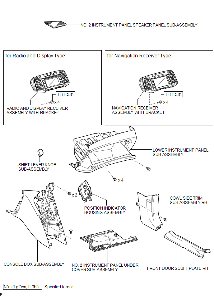
ILLUSTRATION
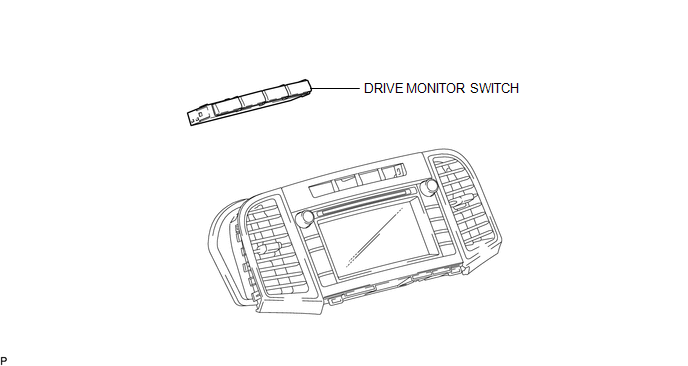

 Inspection
INSPECTION
PROCEDURE
1. INSPECT DRIVE MONITOR SWITCH
(a) Measure the resistance according to the value(s) in the table below.
Standard Resistance:
Tester Connection
Condi ...
Other materials about Toyota Venza:
Installation
INSTALLATION
CAUTION / NOTICE / HINT
HINT:
Use the same procedure for the RH side and LH side.
The procedure listed below is for the LH side.
PROCEDURE
1. INSTALL FRONT AIRBAG SENSOR
(a) Check that the ignition switch is off.
(b) Check ...
System Diagram
SYSTEM DIAGRAM
1. MIRROR CONTROL SYSTEM
Communication Table
Sender
Receiver
Signal / Signal Condition
Line
Main body ECU (driver side junction block assembly)
Outer mirror control EC ...
Front Power Seat does not Operate with Front Power Seat Switch
DESCRIPTION
Signals are input into the position control ECU and switch assembly. The built-in
ECU manages the signals received from the position control ECU and switch assembly,
and operates each motor. If the position control ECU and switch assembly rece ...

0.1244