Toyota Venza: Terminals Of Ecu
TERMINALS OF ECU
1. CHECK MAIN BODY ECU (DRIVER SIDE JUNCTION BLOCK ASSEMBLY)
.png)
(a) Disconnect the 2A and 2F main body ECU (driver side junction block assembly) connectors.
(b) Measure the voltage and resistance according to the value(s) in the table below.
Standard Voltage|
Terminal No. (Symbol) |
Wiring Color |
Terminal Description |
Condition |
Specified Condition |
|---|---|---|---|---|
|
2A-1 - Body ground |
B - Body ground |
Battery power supply |
Always |
11 to 14 V |
|
Terminal No. (Symbol) |
Wiring Color |
Terminal Description |
Condition |
Specified Condition |
|---|---|---|---|---|
|
2F-16 - Body ground |
W-B - Body ground |
Ground |
Always |
Below 1 Ω |
If the result is not as specified, there may be a malfunction on the wire harness side.
(c) Reconnect the 2A and 2F main body ECU (driver side junction block assembly) connectors.
(d) Measure the voltage and resistance according to the value(s) in the table below.
Standard Resistance|
Terminal No. (Symbol) |
Wiring Color |
Terminal Description |
Condition |
Specified Condition |
|---|---|---|---|---|
|
D49-18 (CLTE) - Body ground |
Y - Body ground |
Automatic light control ground |
Always |
Below 1 Ω |
|
Terminal No. (Symbol) |
Wiring Color |
Terminal Description |
Condition |
Specified Condition |
|---|---|---|---|---|
|
2C-7 (PKB) - Body ground |
G - Body ground |
Parking brake switch input |
Parking brake switch on |
Below 1 V |
|
Parking brake switch off |
Pulse generation |
|||
|
2C-23 (DIM) - Body ground |
GR - Body ground |
High beam headlight drive output |
Dimmer switch in high or high flash position |
Below 1 V |
|
Dimmer switch in low position |
Pulse generation |
|||
|
2F-5 (LSR) - Body ground |
Y - Body ground |
Rear door unlock detection switch LH or RH input |
Rear door LH and RH locked |
Pulse generation |
|
Rear door LH or RH unlocked |
Below 1 V |
|||
|
2G-35 (HRLY) - Body ground |
GR - Body ground |
Headlight relay drive output |
Light control switch in head position |
Below 1 V |
|
Light control switch not in head position |
11 to 14 V |
|||
|
2N-2 (HU) - Body ground |
G - Body ground |
Dimmer switch high position signal input |
Dimmer switch in high or high flash position |
Below 1 V |
|
Dimmer switch in low position |
Pulse generation |
|||
|
2O-5 (LSR) - Body ground |
BR - Body ground |
Rear door unlock detection switch LH or RH input |
Rear door LH and RH locked |
Pulse generation |
|
Rear door LH or RH unlocked |
Below 1 V |
|||
|
2O-19 (LCTY) - Body ground |
R - Body ground |
Rear door courtesy light switch LH input |
Rear door LH open |
Below 1 V |
|
Rear door LH closed |
Pulse generation |
|||
|
D49-3 (MILE)*1 - Body ground |
LG - Body ground |
Door mirror foot light drive output |
Door mirror foot light off |
Below 1 V |
|
Door mirror foot light on |
11 to 14 V |
|||
|
D49-7 (RCTY) - Body ground |
GR - Body ground |
Rear door courtesy light switch RH input |
Rear door RH open |
Below 1 V |
|
Rear door RH closed |
Pulse generation |
|||
|
D49-17 (HEAD) - Body ground |
V - Body ground |
Light control switch head position input |
Light control switch in head position |
Below 1 V |
|
Light control switch not in head position |
Pulse generation |
|||
|
D49-19 (CLTS) - Body ground |
V - Body ground |
Automatic light control sensor signal input |
Ignition switch off |
Below 1 V |
|
Automatic light control system operates |
Pulse generation (See waveform 1) |
|||
|
D49-20 (CLTB) - Body ground |
GR - Body ground |
Automatic light control sensor power supply output |
Ignition switch off |
Below 1 V |
|
Ignition switch ON and light control switch in AUTO position |
11 to 14 V |
|||
|
D49-21 (PCTY) - Body ground |
V - Body ground |
Front passenger side door courtesy light switch input |
Front passenger side door open |
Below 1 V |
|
Front passenger side door closed |
Pulse generation |
|||
|
D49-25 (BCTY) - Body ground |
GR - Body ground |
Back door courtesy switch input |
Back door open |
Below 1 V |
|
Back door closed |
11 to 14 V |
|||
|
D49-27 (LSWP) - Body ground |
P - Body ground |
Front passenger side door unlock detection switch input |
Front passenger side door locked |
Pulse generation |
|
Front passenger side door unlocked |
Below 1 V |
|||
|
D49-28 (FFOG) - Body ground |
R - Body ground |
Front fog light switch input |
Front fog light switch on |
Below 1 V |
|
Front fog light switch off |
Pulse generation |
|||
|
D50-4 (FFGO) - Body ground |
GR - Body ground |
Front fog light relay drive output |
Light control switch in head position and front fog light switch on |
Below 1 V |
|
Front fog light switch off |
11 to 14 V |
|||
|
D50-9 (LSWD) - Body ground |
P - Body ground |
Driver side door unlock detection switch input |
Driver side door locked |
Pulse generation |
|
Driver side door unlocked |
Below 1 V |
|||
|
D50-13 (HF) - Body ground |
SB - Body ground |
Dimmer switch high flash position signal input |
Dimmer switch in high flash position |
Below 1 V |
|
Dimmer switch not in high flash position |
Pulse generation |
|||
|
D50-21 (A) - Body ground |
BR - Body ground |
Light control switch AUTO position signal input |
Light control switch in AUTO position |
Below 1 V |
|
Light control switch not in AUTO position |
Pulse generation |
|||
|
D50-23 (TAIL) - Body ground |
R - Body ground |
Light control switch tail position signal input |
Light control switch in tail or head position |
Below 1 V |
|
Light control switch in neither tail nor head position |
Pulse generation |
|||
|
D50-24 (DCTY) - Body ground |
V - Body ground |
Driver side door courtesy light switch input |
Driver side door open |
Below 1 V |
|
Driver side door closed |
Pulse generation |
|||
|
D51-10 (DRL) - Body ground |
G - Body ground |
Daytime running light system drive output |
Daytime running light system operating |
Below 1 V |
|
Daytime running light system not operating |
11 to 14 V |
- *1: w/o Seat Position Memory
If the result is not as specified, the main body ECU (Driver side junction block assembly) may have a malfunction.
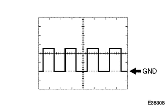
(1) Waveform 1
.png)
|
Item |
Content |
|---|---|
|
Tool setting |
5 V/DIV., 5 ms./DIV. |
HINT:
If the ambient light becomes brighter, width A becomes narrower.
2. CHECK HEADLIGHT LEVELING ECU ASSEMBLY
(a) Disconnect the A40 headlight leveling ECU assembly connector.

(b) Measure the voltage and resistance between the specified terminals of the wire harness side connectors and body ground.
Standard Voltage|
Terminal No. (Symbol) |
Wiring Color |
Terminal Description |
Condition |
Specified Condition |
|---|---|---|---|---|
|
A40-1 (IG) - Body ground |
L - Body ground |
IG power supply |
Ignition switch off |
Below 1 V |
|
Ignition switch ON |
11 to 14 V |
|
Terminal No. (Symbol) |
Wiring Color |
Terminal Description |
Condition |
Specified Condition |
|---|---|---|---|---|
|
A40-9 (E1) - Body ground |
W-B - Body ground |
Ground |
Always |
Below 1 Ω |
If the result is not as specified, there may be a malfunction on the wire harness side.
(c) Reconnect the A40 headlight leveling ECU assembly connector.
(d) Measure the resistance and voltage according to the value(s) in the table below.
Standard Resistance|
Terminal No. (Symbol) |
Wiring Color |
Terminal Description |
Condition |
Specified Condition |
|---|---|---|---|---|
|
A40-21 (SGR) - Body ground |
LG - Body ground |
Rear height control sensor ground |
Always |
Below 1 Ω |
|
A40-23 (RH-) - Body ground |
Y - Body ground |
Leveling motor RH ground |
Always |
Below 1 Ω |
|
A40-24 (LH-) - Body ground |
R - Body ground |
Leveling motor LH ground |
Always |
Below 1 Ω |
|
Terminal No. (Symbol) |
Wiring Color |
Terminal Description |
Condition |
Specified Condition |
|---|---|---|---|---|
|
A40-3 (B2) - Body ground |
LG - Body ground |
Low beam headlight signal input |
Low beam headlights on |
Below 1.5 V |
|
Low beam headlights off |
Above 5 V |
|||
|
A40-15 (PRST) - Body ground |
Y - Body ground |
Initialization signal input |
Terminal LVL and terminal GND of DLC3 connected |
Below 1 V |
|
Terminal LVL and terminal GND of DLC3 not connected |
Approx. 5 V |
|||
|
A40-6 (WNG) - Body ground |
BR - Body ground |
Indicator light drive output |
Indicator light on |
11 to 14 V |
|
Indicator light off |
Below 1 V |
|||
|
A40-10 (RH+) - Body ground |
R - Body ground |
Leveling motor RH power supply |
Ignition switch off |
Below 1 V |
|
Ignition switch ON |
10 to 16 V |
|||
|
A40-11 (LH+) - Body ground |
P - Body ground |
Leveling motor LH power supply |
Ignition switch off |
Below 1 V |
|
Ignition switch ON |
10 to 16 V |
|||
|
A40-12 (SBR) - Body ground |
BR - Body ground |
Rear height control sensor power supply |
Ignition switch off |
Below 1 V |
|
Ignition switch ON |
4.75 to 5.25 V |
|||
|
A40-16 (SPDR) - Body ground |
GR - Body ground |
Vehicle speed signal input |
Vehicle is driven at approx. 20 km/h (12mph) |
Pulse generation (See waveform 1) |
|
A40-17 (RHT) - Body ground |
G - Body ground |
Leveling motor RH operation signal input |
With low beam headlights on, vehicle height not changed |
Below 1 V |
|
With low beam headlights on, change vehicle height and keep for more than 3 seconds. |
1.0 to 14.4 V |
|||
|
A40-18 (LHT) - Body ground |
V - Body ground |
Leveling motor LH operation signal input |
With low beam headlights on, vehicle height not changed |
Below 1 V |
|
With low beam headlights on, change vehicle height and keep for more than 3 seconds. |
1.0 to 14.4 V |
|||
|
A40-19 (SHRL) - Body ground |
BE - Body ground |
Rear height control sensor signal input |
Ignition switch off |
Below 1 V |
|
Ignition switch ON |
0.5 to 4.5 V |
If the result is not as specified, the headlight leveling ECU assembly may have a malfunction.
(1) Waveform 1
|
Item |
Content |
|---|---|
|
Tool setting |
2 V/DIV., 2 ms./DIV. |
3. CHECK AFS ECU (HEADLIGHT SWIVEL ECU ASSEMBLY) (w/ Automatic High Beam System)
(a) Disconnect the D44 AFS ECU (headlight swivel ECU assembly) connector.

(b) Measure the resistance and voltage according to the value(s) in the table below.
Standard Resistance|
Terminal No. (Symbol) |
Wiring Color |
Terminal Description |
Condition |
Specified Condition |
|---|---|---|---|---|
|
D44-22 (E1) - Body ground |
B - Body ground |
AFS ECU (headlight swivel ECU assembly) ground |
Always |
Below 1 Ω |
|
Terminal No. (Symbol) |
Wiring Color |
Terminal Description |
Condition |
Specified Condition |
|---|---|---|---|---|
|
D44-15 (IG) - Body ground |
G - Body ground |
AFS ECU (headlight swivel ECU assembly) power supply |
Ignition switch off |
Below 1 V |
|
Ignition switch ON |
11 to 14 V |
If the result is not as specified, there may be a malfunction on the wire harness side.
(c) Reconnect the D44 AFS ECU (headlight swivel ECU assembly) connector.
(d) Measure the voltage according to the value(s) in the table below.
Standard Voltage|
Terminal No. (Symbol) |
Wiring Color |
Terminal Description |
Condition |
Specified Condition |
|---|---|---|---|---|
|
D44-7 (MPX2) - D44-22 (E1) |
V - B |
Operation check signal |
Ignition switch ON, terminal LVL and GND of DLC3 connected |
Below 1 V |
|
Ignition switch ON, terminal LVL and GND of DLC3 not connected |
Approx. 5 V |
|||
|
D44-10 (SMR) - D44-22 (E1) |
R - B |
LIN communication |
Ignition switch off |
Below 1 V |
|
Ignition switch ON, inner rear view mirror connector disconnected |
Pulse generation (See waveform 1) |
|||
|
D44-12 (CANH) - D44-22 (E1) |
Y - B |
CAN communication |
Ignition switch off |
Below 1 V |
|
Ignition switch ON |
Pulse generation |
|||
|
D44-13 (CANL) - D44-22 (E1) |
W - B |
CAN communication |
Ignition switch off |
Below 1 V |
|
Ignition switch ON |
Pulse generation |
If the result is not as specified, the ECU may have a malfunction.
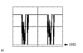
(1) Waveform 1
|
Item |
Content |
|---|---|
|
Tool setting |
2 V/DIV., 20 ms./DIV. |
4. CHECK INNER REAR VIEW MIRROR ASSEMBLY
(a) Disconnect the P12 inner rear view mirror assembly connector.

(b) Measure the resistance and voltage according to the value(s) in the table below.
Standard Resistance|
Terminal No. (Symbol) |
Wiring Color |
Terminal Description |
Condition |
Specified Condition |
|---|---|---|---|---|
|
P12-2 (E)*1 - Body ground |
W-B - Body ground |
Inner rear view mirror assembly ground |
Always |
Below 1 Ω |
|
Terminal No. (Symbol) |
Wiring Color |
Terminal Description |
Condition |
Specified Condition |
|---|---|---|---|---|
|
P12-1 (IG)*1 - Body ground |
Y - Body ground |
Inner rear view mirror assembly power supply |
Ignition switch off |
Below 1 V |
|
Ignition switch ON |
11 to 14 V |
- *1: Automatic Glare-resistant EC Mirror
If the result is not as specified, there may be a malfunction on the wire harness side.
(c) Reconnect the P12 inner rear view mirror assembly connector.
(d) Measure the voltage according to the value(s) in the table below.
Standard Voltage|
Terminal No. (Symbol) |
Wiring Color |
Terminal Description |
Condition |
Specified Condition |
|---|---|---|---|---|
|
P12-3 (LIN)*2 - P12-2 (E) |
R - W-B |
LIN communication |
Ignition switch off |
Below 1 V |
|
Automatic high beam system operates |
Pulse generation (See waveform 1) |
- *2: w/ Automatic High Beam System
If the result is not as specified, the inner rear view mirror assembly may have a malfunction.
(1) Waveform 1
|
Item |
Content |
|---|---|
|
Tool setting |
2 V/DIV., 20 ms./DIV. |
5. CHECK OUTER MIRROR CONTROL ECU ASSEMBLY LH (w/ Seat Position Memory)
(a) Disconnect the I13 outer mirror control ECU assembly LH connector.

(b) Measure the voltage according to the value(s) in the table below.
HINT:
Measure the values on the wire harness side with the connector disconnected.
Standard Voltage|
Tester Connection |
Wiring Color |
Terminal Description |
Condition |
Specified Condition |
|---|---|---|---|---|
|
I13-14 (BDR) - Body ground |
V - Body ground |
Battery power supply |
Ignition switch off |
11 to 14 V |
|
I13-6 (CPUB) - Body ground |
LG - Body ground |
Battery power supply |
Ignition switch off |
11 to 14 V |
|
I13-5 (SIG) - Body ground |
L - Body ground |
Ignition power supply |
Ignition switch ON |
11 to 14 V |
If the result is not as specified, there may be a malfunction on the wire harness side.
(c) Measure the resistance according to the value(s) in the table below.
HINT:
Measure the values on the wire harness side with the connector disconnected.
Standard Resistance|
Tester Connection |
Wiring Color |
Terminal Description |
Condition |
Specified Condition |
|---|---|---|---|---|
|
I13-7 (GND) - Body ground |
W-B - Body ground |
Ground |
Always |
Below 1 Ω |
If the result is not as specified, there may be a malfunction on the wire harness side.
(d) Reconnect the I13 outer mirror control ECU assembly LH connector.
(e) Measure the voltage according to the value(s) in the table below.
Standard Voltage|
Tester Connection |
Wiring Color |
Terminal Description |
Condition |
Specified Condition |
|---|---|---|---|---|
|
I12-2 (LP) - I12-12 (HTR-) |
SB - V |
Door mirror foot light (LH) drive output |
Door mirror foot light off |
Below 1 V |
|
Door mirror foot light on |
11 to 14 V |
6. CHECK OUTER MIRROR CONTROL ECU ASSEMBLY RH (w/ Seat Position Memory)
(a) Disconnect the H13 outer mirror control ECU assembly RH connector.

(b) Measure the voltage according to the value(s) in the table below.
HINT:
Measure the values on the wire harness side with the connector disconnected.
Standard Voltage|
Tester Connection |
Wiring Color |
Terminal Description |
Condition |
Specified Condition |
|---|---|---|---|---|
|
H13-14 (BDR) - Body ground |
R - Body ground |
Battery power supply |
Ignition switch off |
11 to 14 V |
|
H13-6 (CPUB) - Body ground |
B - Body ground |
Battery power supply |
Ignition switch off |
11 to 14 V |
|
H13-5 (SIG) - Body ground |
L - Body ground |
Ignition power supply |
Ignition switch ON |
11 to 14 V |
If the result is not as specified, there may be a malfunction on the wire harness side.
(c) Measure the resistance according to the value(s) in the table below.
HINT:
Measure the values on the wire harness side with the connector disconnected.
Standard Resistance|
Tester Connection |
Wiring Color |
Terminal Description |
Condition |
Specified Condition |
|---|---|---|---|---|
|
H13-7 (GND) - Body ground |
W-B - Body ground |
Ground |
Always |
Below 1 Ω |
If the result is not as specified, there may be a malfunction on the wire harness side.
(d) Reconnect the H13 outer mirror control ECU assembly RH connector.
(e) Measure the voltage according to the value(s) in the table below.
Standard Voltage|
Tester Connection |
Wiring Color |
Terminal Description |
Condition |
Specified Condition |
|---|---|---|---|---|
|
H12-2 (LP) - H12-12 (HTR-) |
SB - V |
Door mirror foot light (RH) drive output |
Door mirror foot light off |
Below 1 V |
|
Door mirror foot light on |
11 to 14 V |
 Problem Symptoms Table
PROBLEM SYMPTOMS TABLE
Use the table below to help determine the cause of problem symptoms. If multiple
suspected areas are listed, the potential causes of the symptoms are listed in order
of pro ...
 Diagnosis System
DIAGNOSIS SYSTEM
1. DESCRIPTION
(a) Lighting system data and the Diagnostic Trouble Codes (DTCs) can be read
from the Data Link Connector 3 (DLC3) of the vehicle. When the system seems to be
mal ...
Other materials about Toyota Venza:
Transmission Range Sensor Circuit Malfunction (PRNDL Input) (P0705)
DESCRIPTION
The park/neutral position switch detects the shift lever position and sends signals
to the TCM.
DTC No.
DTC Detection Condition
Trouble Area
P0705
(A) Any 2 or more signals of the fol ...
On-vehicle Inspection
ON-VEHICLE INSPECTION
PROCEDURE
1. CHECK POWER SOURCE MODE CHANGE FUNCTION
(a) Check the function of the engine switch.
(1) Check that power source mode changes in accordance with the conditions of
the shift position and brake pedal.
Brake Pe ...
Data List / Active Test
DATA LIST / ACTIVE TEST
1. DATA LIST
HINT:
Using the Techstream to read the Data List allows the values or states of switches,
sensors, actuators and other items to be read without removing any parts. This non-intrusive
inspection can be very useful bec ...

0.1202