Toyota Venza: Components
COMPONENTS
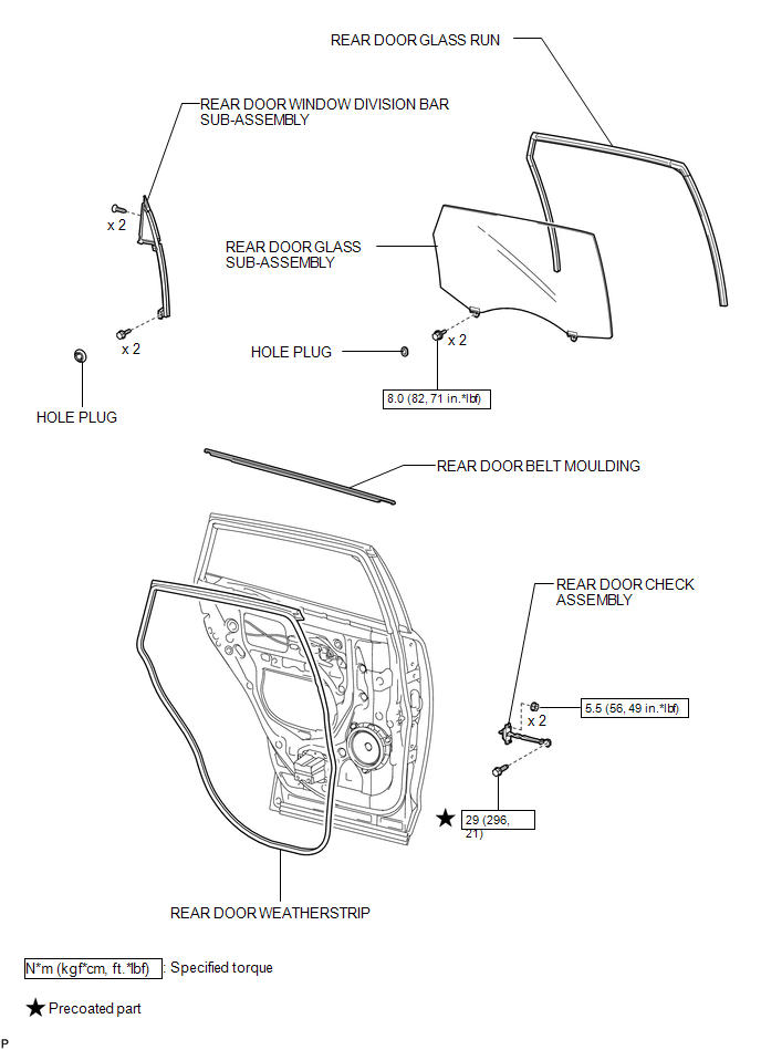
ILLUSTRATION
.png)
ILLUSTRATION

 Removal
REMOVAL
PROCEDURE
1. DISCONNECT CABLE FROM NEGATIVE BATTERY TERMINAL
NOTICE:
When disconnecting the cable, some systems need to be initialized after the cable
is reconnected (See page ).
2. RE ...
Other materials about Toyota Venza:
Installation
INSTALLATION
PROCEDURE
1. INSTALL REAR DOOR BELT MOULDING
(a) Engage the 5 claws to install the rear door belt moulding.
2. INSTALL REAR DOOR GLASS SUB-ASSEMBLY
3. INSTALL REAR DOOR WINDOW DIVIS ...
Seat Position Sensor
Components
COMPONENTS
ILLUSTRATION
On-vehicle Inspection
ON-VEHICLE INSPECTION
CAUTION / NOTICE / HINT
CAUTION:
Be sure to follow the correct removal and installation procedures of the seat
position sensor.
PROCEDURE
1. INSPECT SEAT POSITION S ...
TC and CG Terminal Circuit
DESCRIPTION
Connecting terminals TC and CG of the DLC3 causes the ECU to display the DTC
by blinking the ABS warning and slip indicator lights.
WIRING DIAGRAM
CAUTION / NOTICE / HINT
HINT:
When the warning lights continue to blink, a ground short in t ...

0.1678