Toyota Venza: Components
COMPONENTS
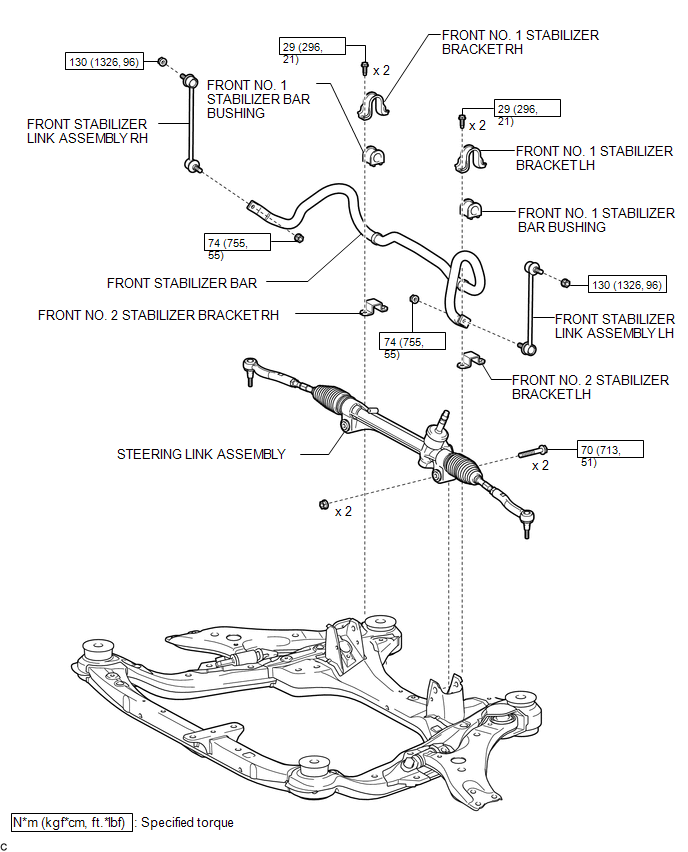
ILLUSTRATION

 Removal
REMOVAL
PROCEDURE
1. REMOVE FRONT WHEELS
2. REMOVE FRONT STABILIZER LINK ASSEMBLY LH
(a) Remove the 2 nuts and front stabilizer link assembly LH.
HINT:
If the ball joint turns tog ...
Other materials about Toyota Venza:
Installation
INSTALLATION
PROCEDURE
1. INSTALL STEERING INTERMEDIATE SHAFT ASSEMBLY
(a) Align the matchmarks on the steering intermediate shaft assembly
and the steering column assembly.
Text in Illustration
*1
Matc ...
Rear Power Window RH Auto Up / Down Function does not Operate with Rear Power
Window Switch RH
DESCRIPTION
If the manual up/down function can be performed but the auto up/down function
cannot, the fail-safe mode may be functioning.
If the power window initialization (See page
) has not been performed, the auto up/down function
will not operate.
...
Selecting the units
Press the “US/M-M” button.
The unit changes each time the button is pressed.
- Liquid crystal display
Small spots or light spots may appear on the display. This phenomenon is characteristic
of liquid crystal displays, and there is no problem to ...

0.134