Toyota Venza: Components
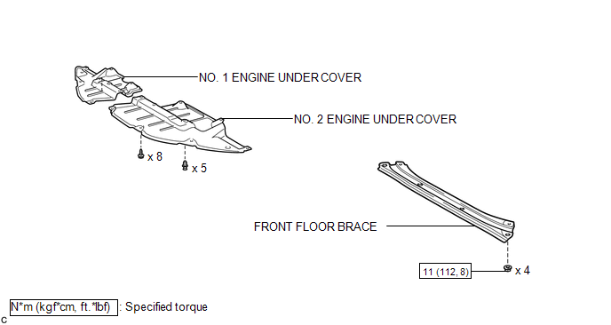
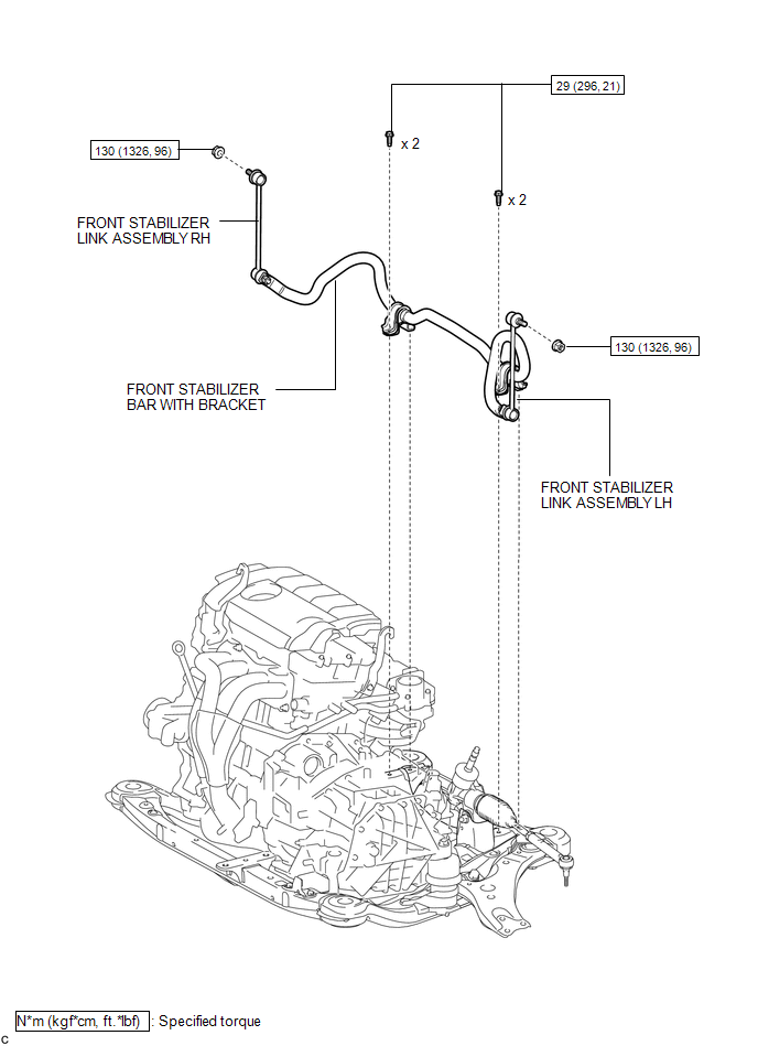
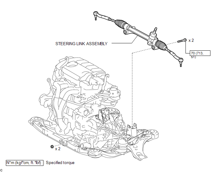
COMPONENTS
ILLUSTRATION
ILLUSTRATION
.png)
ILLUSTRATION
ILLUSTRATION
ILLUSTRATION
.png)
ILLUSTRATION
.png)

 Removal
REMOVAL
CAUTION / NOTICE / HINT
NOTICE:
When disconnecting the steering intermediate shaft assembly and pinion shaft
of the steering gear assembly, be sure to place matchmarks before servicing.
...
Other materials about Toyota Venza:
Passenger Side Buckle Switch Circuit Malfunction (B1771)
DESCRIPTION
The passenger side buckle switch circuit consists of the occupant classification
ECU and front seat inner belt assembly RH.
DTC B1771 is recorded when a malfunction is detected in the passenger side buckle
switch circuit.
Troubleshoot DTC B1 ...
System Description
SYSTEM DESCRIPTION
1. TOUCH SWITCH OUTLINE
(a) Touch switches are touch-sensitive (interactive) switches operated by touching
the screen. When a switch is pressed, the outer film bends in to contact the inner
glass at the pressed position. By doing this, ...
Diagnosis System
DIAGNOSIS SYSTEM
1. DESCRIPTION
When troubleshooting a vehicle with a diagnosis system, the only difference from
the usual troubleshooting procedure is connecting the Techstream to the vehicle
and reading various data output from the vehicle's skid c ...

0.1453