Toyota Venza: Removal
REMOVAL
CAUTION / NOTICE / HINT
NOTICE:
When disconnecting the steering intermediate shaft assembly and pinion shaft of the steering gear assembly, be sure to place matchmarks before servicing.
PROCEDURE
1. PLACE FRONT WHEELS FACING STRAIGHT AHEAD
2. SECURE STEERING WHEEL
|
(a) Secure the steering wheel with the seat belt in order to prevent it from rotating. HINT: This operation is necessary to prevent damage to the spiral cable. |
|
.png)
3. REMOVE FRONT WHEELS
4. REMOVE NO. 1 ENGINE UNDER COVER
5. REMOVE NO. 2 ENGINE UNDER COVER
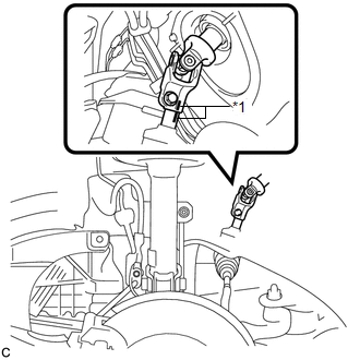
6. SEPARATE STEERING INTERMEDIATE SHAFT ASSEMBLY
|
(a) Put matchmarks on the steering intermediate shaft assembly and steering link assembly. Text in Illustration
|
|
|
(b) Remove the bolt and slide the steering intermediate shaft assembly. |
|
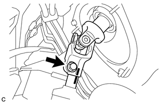
(c) Separate the steering intermediate shaft assembly from the steering link assembly.
7. SEPARATE TIE ROD ASSEMBLY LH
|
(a) Remove the cotter pin and nut. |
|
.png)
|
(b) Install SST to the tie rod end. SST: 09960-20010 09961-02060 NOTICE: Make sure that the upper ends of the tie rod end and SST are aligned. |
|
.png)
(c) Using SST, separate the tie rod end from the steering knuckle.
.png) Text in Illustration
Text in Illustration
|
*1 |
Tie the string without allowing for any slack. |
*2 |
Place the wrench here. |
|
*3 |
Turn |
- |
- |
SST: 09960-20010
09961-02010
CAUTION:
Apply grease to the threads and end of the SST bolt.
NOTICE:
- When securing SST to the steering knuckle, be sure to tighten the string of SST to prevent it from falling.
- Install SST so that A and B are parallel.
- Be sure to place a wrench on the part indicated in the illustration.
- Do not damage the front disc brake dust cover.
- Do not damage the ball joint dust cover.
- Do not damage the steering knuckle.
8. SEPARATE TIE ROD ASSEMBLY RH
HINT:
Perform the same procedure as for the LH side.
9. SEPARATE FRONT STABILIZER LINK ASSEMBLY LH
.gif)
10. SEPARATE FRONT STABILIZER LINK ASSEMBLY RH
HINT:
Perform the same procedure as for the LH side.
11. REMOVE FRONT FLOOR BRACE
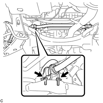
12. SEPARATE FRONT NO. 1 STABILIZER BRACKET LH
|
(a) Remove the 2 bolts and separate the front No. 1 stabilizer bracket LH. |
|
13. SEPARATE FRONT NO. 1 STABILIZER BRACKET RH
HINT:
Perform the same procedure as for the LH side.
14. SEPARATE FRONT STABILIZER BAR WITH BRACKET
(a) Separate the front stabilizer bar with bracket from the front frame assembly.
NOTICE:
Use wire or an equivalent tool to keep the front stabilizer bar with bracket.
15. REMOVE STEERING LINK ASSEMBLY
|
(a) Remove the 2 bolts, 2 nuts and steering link assembly. NOTICE: Because the nut has its own stopper, do not turn the nut. Loosen the bolt with the nut secured. |
|
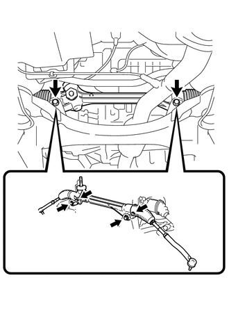
(b) Pull out the steering link assembly towards the left side of the vehicle while lifting the front stabilizer bar with bracket.
16. REMOVE TIE ROD ASSEMBLY LH
|
(a) Put matchmarks on the tie rod assembly LH and steering gear assembly. Text in Illustration
|
|
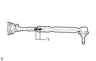
(b) Loosen the lock nut, and remove the tie rod assembly LH and lock nut.
17. REMOVE TIE ROD ASSEMBLY RH
HINT:
Perform the same procedure as for the LH side.
 Components
COMPONENTS
ILLUSTRATION
ILLUSTRATION
ILLUSTRATION
ILLUSTRATION
ILLUSTRATION
ILLUSTRATION
...
 Disassembly
DISASSEMBLY
PROCEDURE
1. REMOVE STEERING RACK BOOT CLIP (for LH Side)
(a) Using pliers, remove the steering rack boot clip.
2. REMOVE STEERING RACK BOOT CLIP (for RH Side)
HINT:
Perform the same ...
Other materials about Toyota Venza:
If the engine will not start
If the engine still does not start after following the correct starting procedure
(, 175) or releasing the steering lock (, 176), confirm the following points.
- The engine will not start even if you are carrying the correct key.
One of the followi ...
Intake Air Control Valve Actuator(for Tcv)
Components
COMPONENTS
ILLUSTRATION
Removal
REMOVAL
PROCEDURE
1. REMOVE INTAKE MANIFOLD
(a) Remove the intake manifold (See page ).
2. REMOVE INTAKE AIR CONTROL VALVE ACTUATOR (for TCV)
(a) Remove the 2 bolts, intake air control valve actuator a ...
Disassembly
DISASSEMBLY
PROCEDURE
1. REMOVE FRONT TRANSAXLE CASE OIL SEAL
(a) Using SST, remove the front transaxle case oil seal from the transaxle
housing.
SST: 09308-00010
2. REMOVE TRANSAXLE CASE OIL ...

0.1549