
Toyota Venza: Components
COMPONENTS
ILLUSTRATION
.png)
ILLUSTRATION
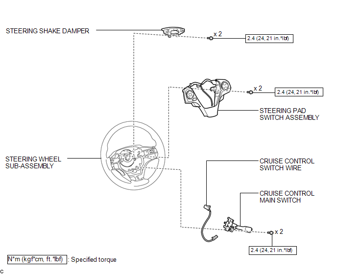
 Steering Wheel
...
 Inspection
INSPECTION
PROCEDURE
1. INSPECT STEERING PAD SWITCH ASSEMBLY
(a) Measure the resistance according to the value(s) in the table below.
Standard Resistance:
Tester Connection
...
Other materials about Toyota Venza:
Problem Symptoms Table
PROBLEM SYMPTOMS TABLE
HINT:
Use the table below to help determine the cause of problem symptoms.
If multiple suspected areas are listed, the potential causes of the symptoms
are listed in order of probability in the "Suspected Area" ...
Low Battery Positive Voltage or Abnormally High Battery Positive Voltage (C1241/41)
DESCRIPTION
If a malfunction is detected in the power supply circuit, the skid control ECU
(housed in the actuator assembly) stores this DTC and the fail-safe function prohibits
ABS operation.
This DTC is stored when the IG1 terminal voltage deviates fro ...
Removal
REMOVAL
PROCEDURE
1. DISCONNECT CABLE FROM NEGATIVE BATTERY TERMINAL
NOTICE:
When disconnecting the cable, some systems need to be initialized after the cable
is reconnected (See page ).
2. REMOVE REAR DOOR INSIDE HANDLE BEZEL PLUG
3. REMOVE REAR P ...

0.1562