Toyota Venza: Inspection
INSPECTION
PROCEDURE
1. INSPECT STEERING PAD SWITCH ASSEMBLY
(a) Measure the resistance according to the value(s) in the table below.
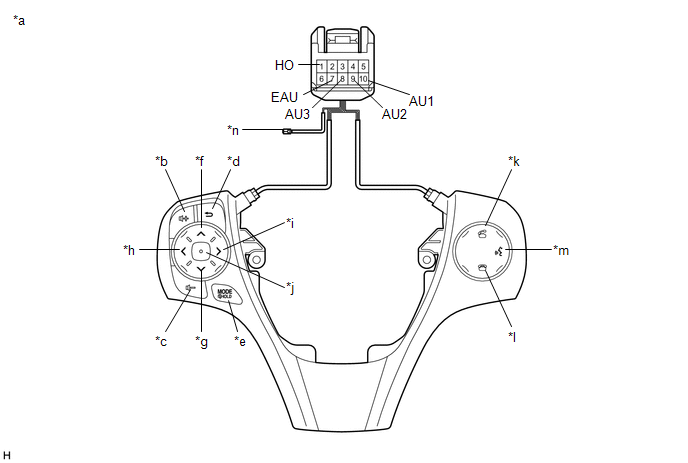
Standard Resistance:
|
Tester Connection |
Condition |
Specified Condition |
|---|---|---|
|
1 (HO) - Terminal-A |
Always |
Below 1 Ω |
|
10 (AU1) - 7 (EAU) |
No switch pushed |
95 to 105 kΩ |
|
Up switch pushed |
Below 2.5 Ω |
|
|
Down switch pushed |
313 to 345 Ω |
|
|
Volume+ switch pushed |
950 to 1050 Ω |
|
|
Volume- switch pushed |
2955 to 3265 Ω |
|
|
9 (AU2) - 7 (EAU) |
No switch pushed |
95 to 105 kΩ |
|
MODE/HOLD switch pushed |
Below 2.5 Ω |
|
|
On hook switch pushed |
313 to 345 Ω |
|
|
Off hook switch pushed |
950 to 1050 Ω |
|
|
Voice switch pushed |
2955 to 3265 Ω |
|
|
8 (AU3) - 7 (EAU) |
No switch pushed |
95 to 105 kΩ |
|
Enter switch pushed |
Below 2.5 Ω |
|
|
Back switch pushed |
313 to 345 Ω |
|
|
Right switch pushed |
950 to 1050 Ω |
|
|
Left switch pushed |
2955 to 3265 Ω |
HINT:
If the result is not as specified, replace the steering pad switch assembly.
Text in Illustration|
*a |
Component without harness connected (Steering Pad Switch Assembly) |
*b |
Volume+ |
|
*c |
Volume- |
*d |
Back |
|
*e |
MODE/HOLD |
*f |
Up |
|
*g |
Down |
*h |
Left |
|
*i |
Right |
*j |
Enter |
|
*k |
Off hook |
*l |
On hook |
|
*m |
Voice |
*n |
Terminal-A |
(b) Check the illumination.
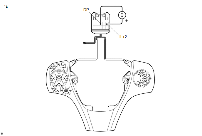
(1) Connect a battery positive (+) lead to terminal IL+2 and a negative (-) lead to terminal -DP of the steering pad switch assembly connector.
(2) Check that the switch illumination comes on.
OK:
Steering pad switch illumination comes on.
HINT:
If the result is not as specified, replace the steering pad switch assembly.
Text in Illustration|
*a |
Component without harness connected (Steering Pad Switch Assembly) |
- |
- |
 Components
COMPONENTS
ILLUSTRATION
ILLUSTRATION
...
 Removal
REMOVAL
CAUTION / NOTICE / HINT
NOTICE:
Do not replace the spiral cable with the battery connected and the ignition
switch ON.
Do not rotate the spiral cable without the steering wh ...
Other materials about Toyota Venza:
Installation
INSTALLATION
PROCEDURE
1. INSTALL BRAKE ACTUATOR ASSEMBLY
(a) Install the brake actuator assembly to the brake actuator bracket
assembly with the 2 nuts.
Torque:
8.0 N·m {82 kgf·cm, 71 in·lbf}
NOTICE:
Do not remov ...
How To Proceed With Troubleshooting
CAUTION / NOTICE / HINT
HINT:
Use the following procedure to troubleshoot the lighting system.
*: Use the Techstream.
PROCEDURE
1.
VEHICLE BROUGHT TO WORKSHOP
NEXT
...
Rear window defogger
Clear the rear window using the defogger.
On/off
The defogger will automatically turn off after 15 or 60 minutes.
This operation time changes according to the ambient temperature and vehicle
speed.
Pressing the switch again also turns the defogger off. ...

0.127