Toyota Venza: Charge Warning Light Comes ON while Driving
PROCEDURE
|
1. |
CHECK LOCK FUNCTION OF CLUTCH PULLEY |
(a) Check the lock function with the pulley installed in the vehicle.
(1) Visually check that the rotor in the generator operates with the engine started.
(b) Check the lock function with the pulley removed from the vehicle.
(1) Remove the generator pulley cap.
|
(2) Hold the generator rotor using SST, and turn the clutch pulley clockwise
to check that the outer ring locks (See page
Text in Illustration
OK: The outer ring locks. |
|
.gif) ).
).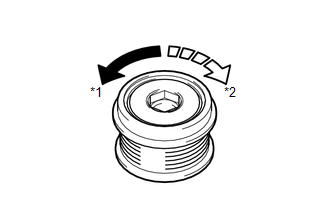
SST: 09820-63021
| NG | .gif) |
REPLACE CLUTCH PULLEY |
|
.gif)
|
2. |
CHECK LOCK OF CLUTCH PULLEY |
(a) Start the engine and visually check for looseness of the clutch pulley.
OK:
The clutch pulley is not loose.
| OK | |
REPLACE GENERATOR ASSEMBLY |
| NG | |
TIGHTEN CLUTCH PULLEY TO THE SPECIFIED TORQUE |
 Problem Symptoms Table
PROBLEM SYMPTOMS TABLE
Use the table below to help determine the cause of problem symptoms.
If multiple suspected areas are listed, the potential causes of the symptoms
are listed in o ...
 Noise Occurs from Generator while Engine is Running
PROCEDURE
1.
CHECK LOOSENESS OF V-RIBBED BELT
(a) Check the tension of the belt by pushing it down with a finger.
OK:
The tension of the belt is enough.
NG ...
Other materials about Toyota Venza:
Pressure Control Solenoid "D" Electrical (Shift Solenoid Valve SLT) (P2716)
DESCRIPTION
Refer to DTC P2714 (See page ).
DTC No.
DTC Detection Condition
Trouble Area
P2716
Open or short is detected in shift solenoid valve SLT circuit for 1 second
or more while driving ...
Removal
REMOVAL
CAUTION / NOTICE / HINT
NOTICE:
w/Camera mirror:The timing of the change between high beams and low beams differs
depending on the light transmission rate of the glass. For this reason, when replacing
the windshield, replace it with an original ...
How To Proceed With Troubleshooting
CAUTION / NOTICE / HINT
HINT:
Use the following procedure to troubleshoot the cruise control system.
*: Use the Techstream.
PROCEDURE
1.
VEHICLE BROUGHT TO WORKSHOP
NEXT
...

0.1294