Toyota Venza: Back Door Entry Lock Function does not Operate
DESCRIPTION
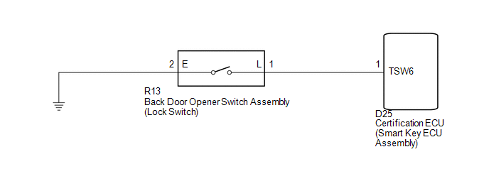
If the back door entry lock function does not operate but the back door open function operates, the communication between the vehicle and key is normal. As a faulty part, the entry lock switch circuit (from the back door opener switch assembly (lock switch) to the certification ECU (smart key ECU assembly)) is suspected.
WIRING DIAGRAM
CAUTION / NOTICE / HINT
NOTICE:
- The smart key system (for entry function) uses a multiplex communication
system (LIN communication system) and CAN communication system. Inspect
the communication function by following How to Proceed with Troubleshooting
(See page
.gif) ). Troubleshoot the smart
). Troubleshoot the smart
key system (for entry function) after confirming that the communication system is functioning properly. - Confirm that another key is not in the cabin.
PROCEDURE
|
1. |
CHECK POWER DOOR LOCK OPERATION |
(a) When the door control switch on the master switch assembly is operated, check
that the doors unlock and lock according to switch operation (See page
).
OK:
Door locks operate normally.
| NG | .gif) |
GO TO POWER DOOR LOCK CONTROL SYSTEM (Proceed to Problem Symptoms Table) |
|
.gif)
|
2. |
READ VALUE USING TECHSTREAM (BACK DOOR OPENER SWITCH) |
(a) Connect the Techstream to the DLC3.
(b) Turn the engine switch on (IG).
(c) Turn the Techstream on.
(d) Enter the following menus: Body Electrical / Smart Key / Data List.
(e) Read the Data List according to the display on the Techstream.
Smart Key (Certification ECU (Smart Key ECU Assembly))|
Tester Display |
Measurement Item/Display |
Normal Condition |
Diagnostic Note |
|---|---|---|---|
|
Tr/B-Door Lock SW |
Back door opener switch assembly (lock switch) / ON or OFF |
ON: Back door opener switch assembly (lock switch) pushed OFF: Back door opener switch assembly (lock switch) not pushed |
- |
OK:
On the Techstream screen, the display changes between ON and OFF as shown in the chart above.
| OK | |
REPLACE CERTIFICATION ECU (SMART KEY ECU ASSEMBLY) |
|
|
3. |
INSPECT BACK DOOR OPENER SWITCH ASSEMBLY |
|
(a) Remove the back door opener switch assembly (See page
|
|
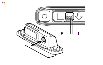
(b) Measure the resistance according to the value(s) in the table below.
Standard Resistance:
|
Tester Connection |
Switch Position |
Specified Condition |
|---|---|---|
|
1 (L) - 2 (E) |
Back door opener switch assembly (lock switch) not pushed (OFF) |
10 kΩ or higher |
|
1 (L) - 2 (E) |
Back door opener switch assembly (lock switch) pushed (ON) |
Below 1 Ω |
|
*1 |
Component without harness connected (Back Door Opener Switch Assembly) |
| NG | |
REPLACE BACK DOOR OPENER SWITCH ASSEMBLY |
|
|
4. |
CHECK HARNESS AND CONNECTOR (CERTIFICATION ECU - BACK DOOR OPENER SWITCH) |
|
(a) Disconnect the certification ECU (smart key ECU assembly) connector. |
|
(b) Measure the resistance according to the value(s) in the table below.
Standard Resistance:
|
Tester Connection |
Condition |
Specified Condition |
|---|---|---|
|
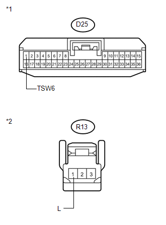
D25-1 (TSW6) - R13-1 (L) |
Always |
Below 1 Ω |
|
D25-1 (TSW6) - Body ground |
Always |
10 kΩ or higher |
|
R13-1 (L) - Body ground |
Always |
10 kΩ or higher |
|
*1 |
Front view of wire harness connector (to Certification ECU (Smart Key ECU Assembly)) |
|
*2 |
Front view of wire harness connector (to Back Door Opener Switch Assembly) |
| OK | |
REPLACE CERTIFICATION ECU (SMART KEY ECU ASSEMBLY) |
| NG | |
REPAIR OR REPLACE HARNESS OR CONNECTOR |
 Back Door Entry Lock and Unlock Functions do not Operate
DESCRIPTION
When the back door entry lock and unlock functions do not operate, one of the
following may be malfunctioning: 1) power door lock control system; 2) outside electrical
key oscillator ...

Other materials about Toyota Venza:
How To Proceed With Troubleshooting
CAUTION / NOTICE / HINT
HINT:
Use the following procedure to troubleshoot the start function.
*: Use the Techstream.
PROCEDURE
1.
VEHICLE BROUGHT TO WORKSHOP
NEXT
...
Lost Communication with AFS ECU (U0182)
DESCRIPTION
DTC No.
DTC Detection Condition
Trouble Area
U0182
No communication from the AFS ECU continues.
AFS ECU branch wire or connector
Power source circuit of AFS E ...
Idle Control System Malfunction (P0505)
DESCRIPTION
The idle speed is controlled by the electronic throttle control system. The electronic
throttle control system is comprised of: 1) the one-valve-type throttle body; 2)
the throttle actuator, which operates the throttle valve; 3) the throttle p ...

0.1195