Toyota Venza: Parts Location
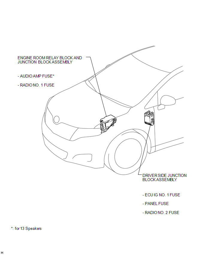
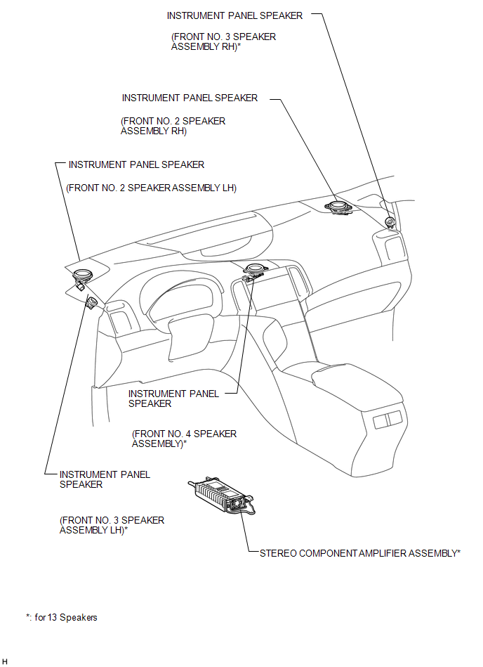
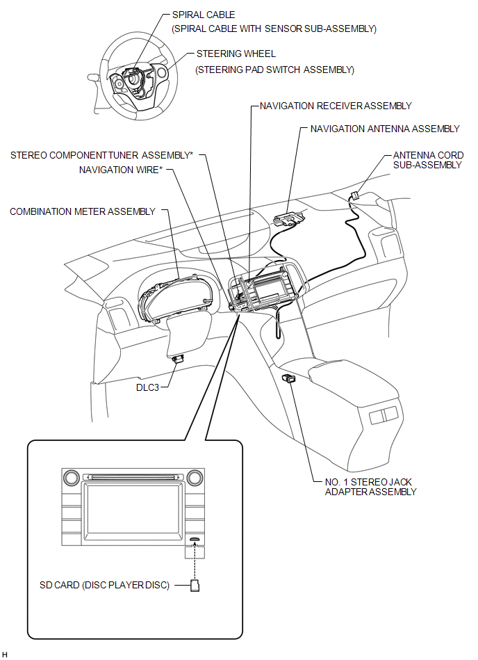
PARTS LOCATION
ILLUSTRATION
ILLUSTRATION
.png)
ILLUSTRATION

ILLUSTRATION
ILLUSTRATION

 Precaution
PRECAUTION
1. PRECAUTION FOR DISCONNECTING CABLE FROM NEGATIVE BATTERY TERMINAL
NOTICE:
After the ignition switch is turned off, the navigation receiver assembly
records various types o ...
Other materials about Toyota Venza:
Types of child restraints
Child restraint systems are classified into the following 3 types according to
the age and size of the child.
► Rear facing -- Infant seat/convertible
seat
► Forward facing -- Convertible seat
► Booster seat
- When install ...
Removal
REMOVAL
PROCEDURE
1. REMOVE AIR CONDITIONING UNIT ASSEMBLY
(See page )
2. REMOVE NO. 1 FINISH PANEL MOUNTING BRACKET
3. REMOVE NO. 2 FINISH PANEL MOUNTING BRACKET
4. REMOVE NO. 3 AIR DUCT SUB-ASSEMBLY
5. REMOVE NO. 2 AIR DUCT SUB-ASSEMBLY
...
Installation
INSTALLATION
PROCEDURE
1. INSTALL REAR POWER POINT SOCKET COVER
(a) Engage the 2 claws to install the rear power point socket cover.
2. INSTALL REAR POWER POINT SOCKET ASSEMBLY
(a) Engag ...

0.1781