Toyota Venza: Engine immobilizer system
The vehicle’s keys have built-in transponder chips that prevent the engine from starting if the key has not been previously registered in the vehicle’s on-board computer.
Never leave the keys inside the vehicle when you leave the vehicle.
Vehicles with smart key system:
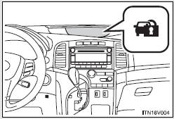
The indicator light flashes after the “ENGINE START STOP” switch has been turned off to indicate that the system is operating.
The indicator light stops flashing after the “ENGINE START STOP” switch has been turned to ACCESSORY or IGNITION ON mode to indicate that the system has been canceled.
Vehicles without smart key system:
The indicator light flashes after the key has been removed from the engine switch to indicate that the system is operating.
The indicator light stops flashing after the registered key has been inserted into the engine switch to indicate that the system has been canceled.
- System maintenance
The vehicle has a maintenance-free type engine immobilizer system.
- Conditions that may cause the system to malfunction
• If the key is in contact with a metallic object.
• If the key is in close proximity to or touching a key to the security system (key with a built-in transponder chip) of another vehicle.
- Certifications for the engine immobilizer system
• For vehicles sold in the U.S.A.
►Vehicles with smart key system FCC ID: NI4TMIMB-1
►Vehicles without smart key system FCC ID: MOZRI-21BTY
NOTE:
This device complies with Part 15 of the FCC Rules. Operation is subject to the
following two conditions: (1) this device may not cause harmful interference, and
(2) this device must accept any interference received, including interference that
may cause undesired operation.
FCC WARNING:
Changes or modifications not expressly approved by the party responsible for compliance
could void the user’s authority to operate the equipment.
• For vehicles sold in Canada Operation is subject to the following two conditions: (1) this device may not cause interference, and (2) this device must accept any interference, including interference that may cause undesired operation of the device.
NOTICE
- To ensure the system operates correctly
Do not modify or remove the system. If modified or removed, the proper operation of the system cannot be guaranteed.

 Alarm
Alarm
The system sounds the alarm and flashes lights when forcible entry is detected.
- Triggering of the alarm
The alarm is triggered in the following situations when the alarm is set.
• A locke ...
Other materials about Toyota Venza:
Bottle holders
► For front seats
► For rear seats
NOTICE
- Items that should not be stowed in the bottle holders
Put the cap on before stowing a bottle. Do not place open bottles in the bottle
holders, or glasses and paper cups containing liquid. ...
Inspection
INSPECTION
PROCEDURE
1. INSPECT CYLINDER BLOCK FOR WARPAGE
(a) Using a precision straightedge and feeler gauge, check the surface
that is in contact with the cylinder head gasket for warpage.
Maximum Warpage:
0.05 mm (0.00197 in.)
I ...
Diagnostic Trouble Code Chart
DIAGNOSTIC TROUBLE CODE CHART
HINT:
If a trouble code is stored during the DTC check, inspect the trouble areas listed
for that code. For details of the code, refer to "See page" below.
1. TRANSPONDER KEY ECU DIAGNOSTIC TROUBLE CODE CHART
Trans ...

0.1545