Toyota Venza: Air Inlet Damper Control Servo Motor Circuit (B1442/42)
DESCRIPTION
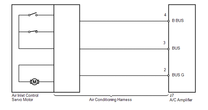
The air inlet control servo motor sends pulse signals to indicate the damper position to the A/C amplifier. The A/C amplifier activates the motor (normal or reverse) based on these signals to move the air inlet mode selection air inlet control damper to any position, which controls the intake air settings (FRESH, FRESH/RECIRCULATION, and RECIRCULATION).
The A/C amplifier communicates with the servo through a communication/driver IC and wiring assembly called the air conditioning harness.
HINT:
Confirm that no mechanical problem is present because this DTC can be output when either a damper link or the damper is mechanically locked.
|
DTC No. |
DTC Detection Condition |
Trouble Area |
|---|---|---|
|
B1442/42 |
Air inlet damper position sensor value does not change even if A/C amplifier operates air inlet control servo motor |
|
WIRING DIAGRAM
PROCEDURE
|
1. |
READ VALUE USING TECHSTREAM |
(a) Connect the Techstream to the DLC3.
(b) Turn the ignition switch to ON.
(c) Turn the Techstream on.
(d) Operate the R/F (Recirculation/Fresh) switch.
(e) Enter the following menus: Body / Air Conditioner / Data List.
(f) Check the value(s) by referring to the table below.
Air Conditioner|
Tester Display |
Measurement Item/Range |
Normal Condition |
Diagnostic Note |
|---|---|---|---|
|
Air Inlet Damper Targ Pulse |
Air inlet servo motor target pulse / Min.: 0, Max.: 255 |
RECIRCULATION: 7 (pulse) FRESH: 28 (pulse) |
- |
OK:
The display is as specified in the Normal Condition column.
|
Result |
Proceed to |
|---|---|
|
NG |
A |
|
OK (When troubleshooting according to Problem Symptoms Table) |
B |
|
OK (When troubleshooting according to the DTC) |
C |
| B | .gif) |
PROCEED TO NEXT SUSPECTED AREA SHOWN IN PROBLEM SYMPTOMS TABLE |
| C | |
REPLACE A/C AMPLIFIER |
|
.gif)
|
2. |
PERFORM ACTIVE TEST USING TECHSTREAM |
(a) Connect the Techstream to the DLC3.
(b) Turn the ignition switch to ON.
(c) Turn the Techstream on.
(d) Enter the following menus: Body / Air Conditioner / Active Test.
(e) Check the operation by referring to the table below.
Air Conditioner|
Tester Display |
Test Part |
Control Range |
Diagnostic Note |
|---|---|---|---|
|
Air Inlet Damper Targ Pulse |
Air inlet damper target pulse |
Min.: 0, Max.: 255 |
- |
OK:
Recirculation damper position changes in accordance with each control range.
| OK | |
REPLACE A/C AMPLIFIER |
|
|
3. |
INSPECT AIR INLET CONTROL SERVO MOTOR |
(a) Replace the air inlet control servo motor (See page
.gif) ).
).
HINT:
Since the servo motor cannot be inspected while it is removed from the vehicle, replace the servo motor with a new or a known good one and check that the condition returns to normal.
(b) Check for the DTC.
|
Result |
Proceed to |
|---|---|
|
DTC B1442/42 is output |
A |
|
DTC B1442/42 is not output |
B |
| B | |
REPLACE AIR INLET CONTROL SERVO MOTOR |
|
|
4. |
INSPECT AIR CONDITIONING HARNESS |
(a) Replace the air conditioning harness (See page
).
HINT:
Since the air conditioning harness cannot be inspected while it is removed from the vehicle, replace the air conditioning harness with a new or a known good one and check that the condition returns to normal.
(b) Check for the DTC.
|
Result |
Proceed to |
|---|---|
|
DTC B1442/42 is output |
A |
|
DTC B1442/42 is not output |
B |
| A | |
REPLACE A/C AMPLIFIER |
| B | |
REPLACE AIR CONDITIONING HARNESS |
 Air Mix Damper Control Servo Motor Circuit (Driver Side) (B1446/46)
DESCRIPTION
The air mix control servo motor sends pulse signals to indicate the damper position
to the A/C amplifier. The A/C amplifier activates the motor (normal or reverse)
based on these sign ...
 Air Outlet Damper Control Servo Motor Circuit (B1443/43)
DESCRIPTION
The air outlet control servo motor sends pulse signals to indicate the damper
position to the A/C amplifier. The A/C amplifier activates the motor (normal or
reverse) based on these s ...
Other materials about Toyota Venza:
Problem Symptoms Table
PROBLEM SYMPTOMS TABLE
HINT:
Use the table below to help determine the cause of problem symptoms.
If multiple suspected areas are listed, the potential causes of the symptoms
are listed in order of probability in the "Suspected Area" ...
Fuel Sender Gauge Assembly
Components
COMPONENTS
ILLUSTRATION
Removal
REMOVAL
PROCEDURE
1. DISCHARGE FUEL SYSTEM PRESSURE
(a) Discharge fuel system pressure (See page
).
2. DISCONNECT CABLE FROM NEGATIVE BATTERY TERMINAL
NOTICE:
When disconnecting the cable, some syste ...
Components
COMPONENTS
ILLUSTRATION
ILLUSTRATION
ILLUSTRATION
ILLUSTRATION
ILLUSTRATION
ILLUSTRATION
ILLUSTRATION
ILLUSTRATION
ILLUSTRATION
ILLUSTRATION
...

0.1298