Toyota Venza: Air Fuel Ratio Sensor
Components
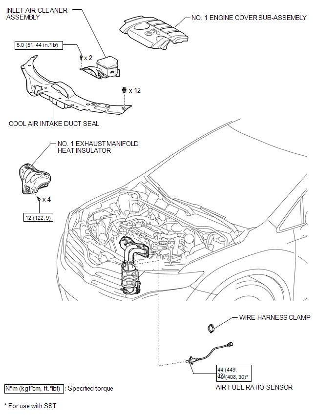
COMPONENTS
ILLUSTRATION
Removal
REMOVAL
PROCEDURE
1. REMOVE NO. 1 ENGINE COVER SUB-ASSEMBLY
.gif)
2. REMOVE COOL AIR INTAKE DUCT SEAL
3. REMOVE INLET AIR CLEANER ASSEMBLY
4. REMOVE NO. 1 EXHAUST MANIFOLD HEAT INSULATOR
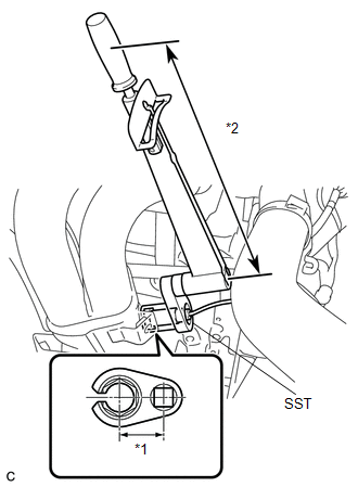
5. REMOVE AIR FUEL RATIO SENSOR
|
(a) Disconnect the air fuel ratio sensor connector. |
|
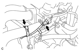
(b) Remove the wire harness clamp.
|
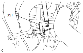
(c) Using SST, remove the air fuel ratio sensor from the exhaust manifold. SST: 09224-00011 |
|
Inspection
INSPECTION
PROCEDURE
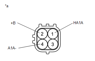
1. INSPECT AIR FUEL RATIO SENSOR (for Bank 1 Sensor 1)
|
(a) Measure the resistance according to the value(s) in the table below. Standard Resistance:
If the result is not as specified, replace the air fuel ratio sensor. Text in Illustration
|
|
Installation
INSTALLATION
PROCEDURE
1. INSTALL AIR FUEL RATIO SENSOR
|
(a) Using SST, install the air fuel ratio sensor to the exhaust manifold. Text in Illustration
SST: 09224-00011 Torque: without SST : 44 N·m {449 kgf·cm, 32 ft·lbf} with SST : 40 N·m {408 kgf·cm, 30 ft·lbf} NOTICE:
HINT: Perform "Inspection After Repair" after replacing the air fuel ratio
sensor (See page |
|
|
(b) Connect the air fuel ratio sensor connector. |
|
.png)
(c) Install the wire harness clamp.
2. INSPECT FOR EXHAUST GAS LEAK
3. INSTALL NO. 1 EXHAUST MANIFOLD HEAT INSULATOR
.gif)
4. INSTALL INLET AIR CLEANER ASSEMBLY
5. INSTALL COOL AIR INTAKE DUCT SEAL
6. INSTALL NO. 1 ENGINE COVER SUB-ASSEMBLY
 Accelerator Pedal
Components
COMPONENTS
ILLUSTRATION
On-vehicle Inspection
ON-VEHICLE INSPECTION
PROCEDURE
1. INSPECT ACCELERATOR PEDAL SENSOR ASSEMBLY
(a) Connect the Techstream to the DLC3.
(b) Turn the ...

Other materials about Toyota Venza:
Disabling the TRAC system
If the vehicle gets stuck in mud, dirt or snow, the TRAC system may reduce power
from the engine to the wheels. Pressing
to turn the system off may make it
easier for you to rock the vehicle in order to free it.
To turn the TRAC system off, quickly pr ...
Low Power Supply Voltage (C1241/94)
DESCRIPTION
If a malfunction in the power source circuit occurs, or a malfunction in communication
with the skid control ECU or in a speed sensor occurs, the AWD control ECU will
prohibit operations by the fail-safe function.
DTC No.
...
Removal
REMOVAL
CAUTION / NOTICE / HINT
NOTICE:
If automatic transaxle assembly parts are replaced, refer to Parts Replacement
Compensation Table to determine if any additional operations are necessary (See
page ).
PROCEDURE
1. DISCHARGE FUEL PRESSURE
See p ...

0.2035