Toyota Venza: Air Conditioning Amplifier
Components
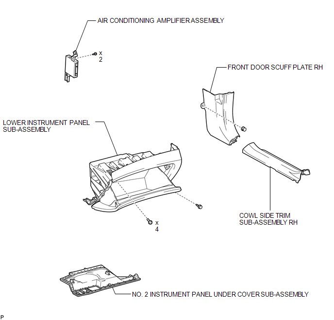
COMPONENTS
ILLUSTRATION
Installation
INSTALLATION
PROCEDURE
1. INSTALL AIR CONDITIONING AMPLIFIER ASSEMBLY
|
(a) Install the air conditioning amplifier assembly with the 2 screws. |
|
(b) Connect each connector.
NOTICE:
Be careful when installing the air conditioning amplifier assembly. If the air conditioning amplifier assembly is dropped, replace it with a new one.
2. INSTALL LOWER INSTRUMENT PANEL SUB-ASSEMBLY
.gif)
3. INSTALL NO. 2 INSTRUMENT PANEL UNDER COVER SUB-ASSEMBLY
4. INSTALL COWL SIDE TRIM SUB-ASSEMBLY RH
HINT:
Use the same procedure for the RH side and the LH side (See page
).
5. INSTALL FRONT DOOR SCUFF PLATE RH
HINT:
Use the same procedure for the RH side and the LH side (See page
).
6. CONNECT CABLE TO NEGATIVE BATTERY TERMINAL
NOTICE:
When disconnecting the cable, some systems need to be initialized after the cable
is reconnected (See page ).
Removal
REMOVAL
PROCEDURE
1. DISCONNECT CABLE FROM NEGATIVE BATTERY TERMINAL
NOTICE:
When disconnecting the cable, some systems need to be initialized after the cable
is reconnected (See page .gif) ).
).
2. REMOVE FRONT DOOR SCUFF PLATE RH
HINT:
Use the same procedure for the RH side and the LH side (See page
).
3. REMOVE COWL SIDE TRIM SUB-ASSEMBLY RH
HINT:
Use the same procedure for the RH side and the LH side (See page
).
4. REMOVE NO. 2 INSTRUMENT PANEL UNDER COVER SUB-ASSEMBLY
5. REMOVE LOWER INSTRUMENT PANEL SUB-ASSEMBLY
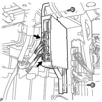
6. REMOVE AIR CONDITIONING AMPLIFIER ASSEMBLY
|
(a) Disconnect each connector. |
|
.png)
(b) Remove the 2 screws and air conditioning amplifier assembly.
NOTICE:
Be careful when removing the air conditioning amplifier assembly. If the air conditioning amplifier assembly is dropped, replace it with a new one.

 Air Conditioning Panel
Components
COMPONENTS
ILLUSTRATION
Installation
INSTALLATION
PROCEDURE
1. INSTALL AIR CONDITIONING CONTROL ASSEMBLY
(a) Connect the connector.
(b) Engage the 2 clips and 4 gui ...
Other materials about Toyota Venza:
Diagnosis System
DIAGNOSIS SYSTEM
1. DESCRIPTION
(a) Front power seat control system (w/ Memory) data and Diagnostic Trouble Codes
(DTCs) can be read through the Data Link Connector 3 (DLC3) of the vehicle. When
the system seems to be malfunctioning, use the Techstream t ...
Installation
INSTALLATION
CAUTION / NOTICE / HINT
HINT:
Use the same procedure for the RH side and LH side.
The procedure listed below is for the LH side.
PROCEDURE
1. SECURE REAR SHOCK ABSORBER WITH COIL SPRING
2. INSTALL REAR LOWER COIL SPRING ...
Air Conditioning Pressure Sensor
Components
COMPONENTS
ILLUSTRATION
Installation
INSTALLATION
PROCEDURE
1. INSTALL AIR CONDITIONING PRESSURE SENSOR
(a) Sufficiently apply compressor oil to a new air conditioning pressure
sensor.
Compressor oil:
ND-OIL 8 or e ...

0.1333