Toyota Venza: Air Conditioning Control Panel Circuit
DESCRIPTION
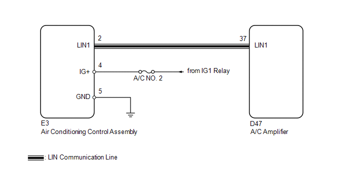
This circuit consists of the air conditioning control assembly and the A/C amplifier. When the air conditioning control assembly is operated, signals are transmitted to the A/C amplifier through the LIN communication system.
If the LIN communication system malfunctions, the A/C amplifier does not operate even if the air conditioning control assembly is operated.
WIRING DIAGRAM
CAUTION / NOTICE / HINT
NOTICE:
Inspect the fuses for circuits related to this system before performing the following inspection procedure.
PROCEDURE
|
1. |
CHECK HARNESS AND CONNECTOR (AIR CONDITIONING CONTROL ASSEMBLY - BODY GROUND) |
(a) Disconnect the air conditioning control assembly connector.
(b) Measure the resistance according to the value(s) in the table below.
Standard Resistance:
|
Tester Connection |
Condition |
Specified Condition |
|---|---|---|
|
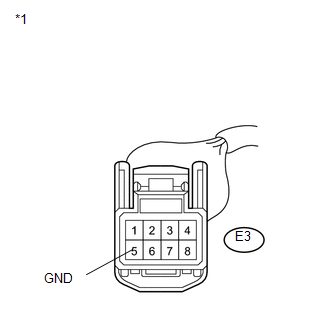
E3-5 (GND) - Body ground |
Always |
Below 1 Ω |
|
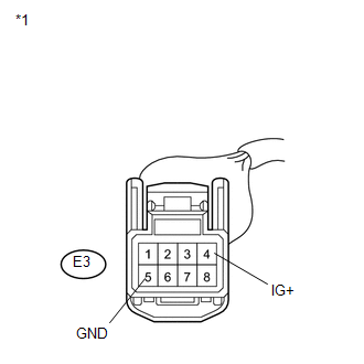
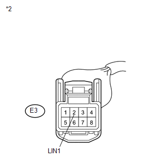
*1 |
Front view of wire harness connector (to Air Conditioning Control Assembly) |
| NG | .gif) |
REPAIR OR REPLACE HARNESS OR CONNECTOR |
|
.gif)
|
2. |
CHECK HARNESS AND CONNECTOR (AIR CONDITIONING CONTROL ASSEMBLY - BATTERY) |
|
(a) Measure the voltage according to the value(s) in the table below. Standard Voltage:
|
|
| NG | |
REPAIR OR REPLACE HARNESS OR CONNECTOR |
|
|
3. |
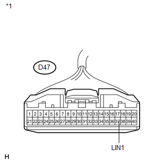
CHECK HARNESS AND CONNECTOR (A/C AMPLIFIER - AIR CONDITIONING CONTROL ASSEMBLY) |
|
(a) Disconnect the A/C amplifier connector. |
|
|
(b) Measure the resistance according to the value(s) in the table below. Standard Resistance:
|
|
| NG | |
REPAIR OR REPLACE HARNESS OR CONNECTOR |
|
|
4. |
INSPECT AIR CONDITIONING CONTROL ASSEMBLY |
(a) Replace the air conditioning control assembly (See page
.gif) ).
).
HINT:
Since the air conditioning control assembly cannot be inspected while it is removed from the vehicle, replace the air conditioning control assembly with a new or a known good one and check that the condition returns to normal.
(b) Operate the air conditioning control assembly to check that it functions properly.
|
Result |
Proceed to |
|---|---|
|
Air conditioning control assembly malfunctions |
A |
|
Air Conditioning control assembly functions properly |
B |
| A | |
PROCEED TO NEXT SUSPECTED AREA SHOWN IN PROBLEM SYMPTOMS TABLE |
| B | |
REPLACE AIR CONDITIONING CONTROL ASSEMBLY |
 Ambient Temperature Sensor Circuit (B1412/12)
DESCRIPTION
The ambient temperature sensor is installed in front of the condenser. It detects
the ambient temperature to control air conditioning AUTO mode. This sensor is connected
to the A/C am ...
 Air Conditioning Compressor Magnetic Clutch Circuit
DESCRIPTION
When the A/C amplifier is turned on, a magnetic clutch ON signal is sent from
the MGC terminal of the A/C amplifier. Then, the MGC relay turns on to operate the
magnetic clutch.
WIRI ...
Other materials about Toyota Venza:
Removal
REMOVAL
CAUTION / NOTICE / HINT
HINT:
Use the same procedure for the RH side and LH side.
The procedure listed below is for the LH side.
PROCEDURE
1. REMOVE REAR WHEEL
2. SEPARATE REAR SPEED SENSOR
3. REMOVE REAR AXLE SHAFT NUT
...
Precaution
PRECAUTION
NOTICE:
When disconnecting the cable from the negative (-) battery terminal, initialize
the following systems after the cable is reconnected.
System Name
See Procedure
Power back door system
...
Installation
INSTALLATION
PROCEDURE
1. INSTALL PARKING BRAKE SWITCH ASSEMBLY
(a) Install the parking brake switch assembly with the screw.
Torque:
0.9 N·m {9 kgf·cm, 8 in·lbf}
2. INSTALL PARKING BRAKE ...

0.1748