Toyota Venza: Vehicle Speed or Engine Speed Signal Malfunction (C2173/73)
DESCRIPTION
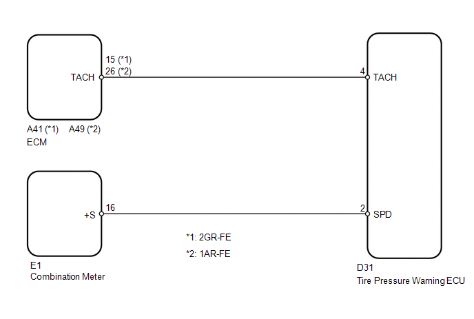
The tire pressure warning ECU receives a vehicle speed signal from the combination meter and an engine speed signal from the ECM. The tire pressure warning ECU uses these signals to detect DTCs C2121/21 to C2124/24 (No Signal from Transmitter).
|
DTC No. |
DTC Detection Condition |
Trouble Area |
|---|---|---|
|
C2173/73 |
When either of the following conditions is met for a total of 15 minutes: (a) No engine speed signal while vehicle speed is 8 km/h (5 mph) or more (b) No vehicle speed signal while engine speed is a specified value |
|
HINT:
This DTC is set at the same time as DTCs C2121/21 to C2124/24 are being set.
WIRING DIAGRAM
CAUTION / NOTICE / HINT
NOTICE:
- When replacing the tire pressure warning ECU, read the transmitter IDs stored in the old ECU using the Techstream and write them down before removal.
- It is necessary to perform registration (See page
.gif) ) of the transmitter IDs into the tire
) of the transmitter IDs into the tire
pressure warning ECU if the ECU has been replaced.
PROCEDURE
|
1. |
PERFORM SIGNAL CHECK (VEHICLE SPEED SIGNAL AND ENGINE SPEED SIGNAL) |
(a) Enter the signal check mode in Test Mode Procedure (See page
).
(b) Drive the vehicle at 20 km/h (12 mph) or more for 10 seconds to clear DTC C2191/91.
(c) Start the engine and allow it to run at 1000 rpm for 3 seconds or more to clear DTC C2194/94.
(d) Check for signal check DTCs.
|
Result |
Proceed to |
|---|---|
|
DTCs C2191/91 and C2194/94 are cleared |
A |
|
DTC C2191/91 is output |
B |
|
DTC C2194/94 is output |
C |
HINT:
DTCs C2181/81 to C2184/84 (Transmitter ID not Received) are output at this time, but they are not related to this check.
| A | .gif) |
USE SIMULATION METHOD TO CHECK |
| B | |
GO TO DTC C2191/91 |
| C | |
GO TO DTC C2194/94 |
 Diagnostic Trouble Code Chart
DIAGNOSTIC TROUBLE CODE CHART
HINT:
If a trouble code is displayed during the DTC check, inspect the circuit listed
for that code. For details of each code, refer to the relevant page listed under ...
 Receiver Error (C2176/76)
DESCRIPTION
The signals are transmitted to the tire pressure warning antenna and receiver
on the body as radio waves and then sent to the tire pressure warning ECU.
DTC No.
D ...
Other materials about Toyota Venza:
Manual Shifting Test
MANUAL SHIFTING TEST
1. PERFORM MANUAL SHIFTING TEST
HINT:
Using this test, it can be determined whether a problem is in an electrical
circuit or if it is a mechanical problem in the transaxle.
If any abnormalities are found in the following ...
Problem Symptoms Table
PROBLEM SYMPTOMS TABLE
HINT:
Use the table below to help determine the cause of problem symptoms.
If multiple suspected areas are listed, the potential causes of the symptoms
are listed in order of probability in the "Suspected Area" ...
Installation
INSTALLATION
PROCEDURE
1. INSTALL NAVIGATION RECEIVER ASSEMBLY
2. INSTALL NO. 2 RADIO RECEIVER BRACKET
(a) Install the No. 2 radio receiver bracket with the 4 screws.
Torque:
5.0 N·m {51 kgf·cm, 44 in·lbf}
3. INSTALL NO. 1 RADIO RECEIVER BRACKET
(a ...

0.1632