Toyota Venza: System Diagram
SYSTEM DIAGRAM
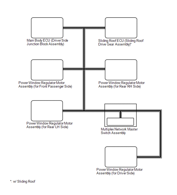
1. DOOR BUS LINES
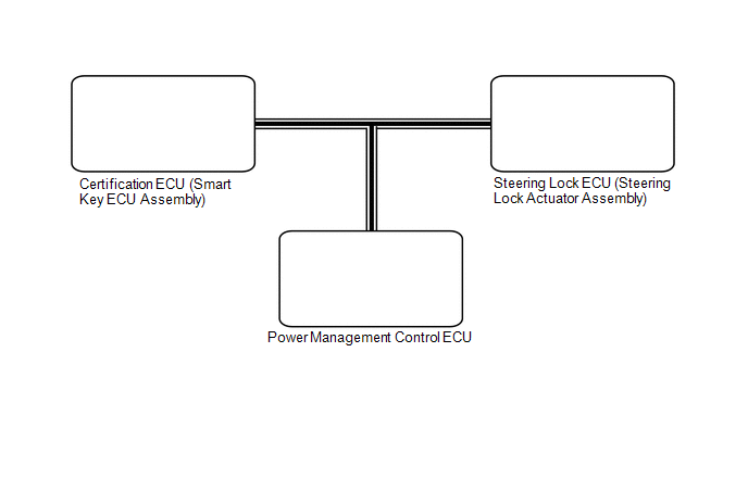
2. CERTIFICATION BUS LINES [w/ Smart Key System]
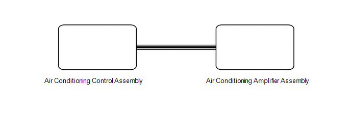
3. AIR CONDITIONING BUS LINES
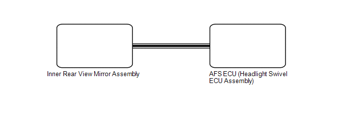
4. LIGHTING BUS LINES [w/ Smart Beam]
 System Description
SYSTEM DESCRIPTION
1. LIN COMMUNICATION SYSTEM DESCRIPTION
The LIN communication system is used for communication between the components
in the table below. If communication cannot be performed th ...
 How To Proceed With Troubleshooting
CAUTION / NOTICE / HINT
HINT:
Use the following procedure to troubleshoot the LIN communication system.
*: Use the Techstream.
PROCEDURE
1.
VEHICLE BROU ...
Other materials about Toyota Venza:
Speed Sensor(when Using The Engine Support Bridge)
Components
COMPONENTS
ILLUSTRATION
Removal
REMOVAL
PROCEDURE
1. REMOVE TRANSMISSION VALVE BODY ASSEMBLY
See page
2. REMOVE SPEED SENSOR
(a) Disconnect the speed sensor connector.
(b) Remove the 2 bolts and speed sensor from the tra ...
Speed Signal Malfunction (B15C2)
DESCRIPTION
The navigation receiver assembly receives a vehicle speed signal from the combination
meter assembly and information from the navigation antenna assembly, and then adjusts
the vehicle position.
The navigation receiver assembly stores this DTC ...
Customize Parameters
CUSTOMIZE PARAMETERS
1. CUSTOMIZE LIGHTING SYSTEM (EXT)
HINT:
The following items can be customized.
NOTICE:
When the customer requests a change in a function, first make sure that
the function can be customized.
Be sure to make a note of ...

0.1282