Toyota Venza: Satellite Radio Antenna
Components
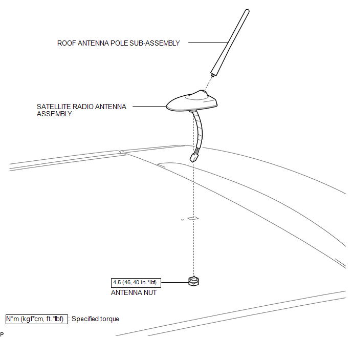
COMPONENTS
ILLUSTRATION
.png)
ILLUSTRATION
Removal
REMOVAL
PROCEDURE
1. REMOVE ROOF HEADLINING ASSEMBLY
(See page .gif) )
)
2. REMOVE ROOF ANTENNA POLE SUB-ASSEMBLY
3. REMOVE SATELLITE RADIO ANTENNA ASSEMBLY
|
(a) Disconnect the connector. |
|
.png)
|
(b) Remove the antenna nut. |
|
.png)
|
(c) Disengage the 2 claws and remove the satellite radio antenna assembly. |
|
.png)
Installation
INSTALLATION
PROCEDURE
1. INSTALL SATELLITE RADIO ANTENNA ASSEMBLY
(a) Engage the 2 claws to the vehicle body to temporarily install the satellite radio antenna assembly.
|
(b) Place the antenna cord in the cutout of the antenna nut. Text in Illustration
|
|
.png)
(c) Install the satellite radio antenna assembly with the antenna nut.
Torque:
4.5 N·m {46 kgf·cm, 40 in·lbf}
(d) Connect the connector.
2. INSTALL ROOF ANTENNA POLE SUB-ASSEMBLY
.gif)
3. INSTALL ROOF HEADLINING ASSEMBLY
(See page )
 Installation
INSTALLATION
PROCEDURE
1. INSTALL REAR NO. 2 SPEAKER ASSEMBLY (for 13 Speakers)
(a) Install the rear No. 2 speaker assembly with the 2 screws.
...

Other materials about Toyota Venza:
Adjustment
ADJUSTMENT
PROCEDURE
1. INSPECT SHIFT LEVER POSITION
(a) When moving the lever from P to R with the ignition switch ON and the brake
pedal depressed, make sure that the shift lever moves smoothly and moves correctly
into position.
(b) Start the engine ...
System Description
SYSTEM DESCRIPTION
1. ILLUMINATED ENTRY SYSTEM
(a) The illuminated entry system has the following control functions:
Control
Outline
Lights that Operate
Actuation Area-linked*2
When a registered k ...
System Diagram
SYSTEM DIAGRAM
Communication Method
Transmitting ECU
Receiver
Signal
Communication Method
Main body ECU (Driver Side Junction Block Assembly)
Power back door ECU (Power back door motor ...

0.1387