Toyota Venza: Removal
REMOVAL
CAUTION / NOTICE / HINT
HINT:
- Use the same procedure for the RH side and LH side.
- The procedure listed below is for the LH side.
PROCEDURE
1. PRECAUTION
CAUTION:
Be sure to read Precaution thoroughly before servicing (See page
.gif) ).
).
2. DISCONNECT CABLE FROM NEGATIVE BATTERY TERMINAL
CAUTION:
Wait at least 90 seconds after disconnecting the cable from the negative (-) battery terminal to disable the SRS system.
NOTICE:
When disconnecting the cable, some systems need to be initialized after the cable
is reconnected (See page ).
3. REMOVE FRONT DOOR INSIDE HANDLE BEZEL PLUG
4. REMOVE POWER WINDOW REGULATOR MASTER SWITCH ASSEMBLY WITH FRONT DOOR ARMREST BASE PANEL (for Driver Side)
5. REMOVE POWER WINDOW REGULATOR SWITCH ASSEMBLY WITH FRONT DOOR ARMREST BASE PANEL (for Front Passenger Side)
6. REMOVE COURTESY LIGHT ASSEMBLY
7. REMOVE FRONT DOOR TRIM BOARD SUB-ASSEMBLY
8. REMOVE DOOR SIDE AIRBAG SENSOR
(a) Check that the ignition switch is off.
(b) Check that the cable is disconnected from the negative (-) battery terminal.
CAUTION:
Wait at least 90 seconds after disconnecting the cable from the negative (-) battery terminal to disable the SRS system.
(c) Disconnect the connector.
NOTICE:
When disconnecting the airbag connector, take care not to damage the airbag wire harness.
(1) Push and hold the white housing lock, and slide the yellow outer connector locking sleeve.
.png) Text in Illustration
Text in Illustration
|
*1 |
Housing Lock |
*2 |
Outer Connector Locking Sleeve |
(2) Push and hold the white housing lock again, and slide the yellow outer connector locking sleeve to disconnect the connector.
|
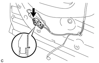
(d) Remove the bolt and door side airbag sensor. NOTICE: Loosen the bolt while holding the door side airbag sensor because the door side airbag sensor pin (stopper) is easily damaged. |
|
 On-vehicle Inspection
ON-VEHICLE INSPECTION
CAUTION / NOTICE / HINT
CAUTION:
Be sure to follow the correct removal and installation procedures of the door
side airbag sensor.
PROCEDURE
1. INSPECT DOOR SIDE AIRBAG SE ...
 Installation
INSTALLATION
CAUTION / NOTICE / HINT
HINT:
Use the same procedure for the RH side and LH side.
The procedure listed below is for the LH side.
PROCEDURE
1. INSTALL DOOR SIDE AIRB ...
Other materials about Toyota Venza:
Lubrication system
- Engine oil selection
“Toyota Genuine Motor Oil” is used in your Toyota vehicle. Use Toyota approved
“Toyota Genuine Motor Oil” or equivalent to satisfy the following grade and viscosity.
Oil grade: ILSAC GF-5 multigrade engine oil
Recomm ...
Power Back Door cannot be Operated Using Any Switch
DESCRIPTION
When the power back door cannot be operated using any switch, one of the following
may be the cause: 1) initialization of the power back door ECU (power back door
motor unit), 2) power back door touch sensor circuit, 3) power back door main sw ...
Tcm
Components
COMPONENTS
ILLUSTRATION
Removal
REMOVAL
CAUTION / NOTICE / HINT
NOTICE:
If automatic transmission parts are replaced, refer to Parts Replacement Compensation
Table to determine if any additional operations are necessary (See page
). ...

0.1549