Toyota Venza: Power Mirror cannot be Adjusted with Power Mirror Switch
SYSTEM DESCRIPTION
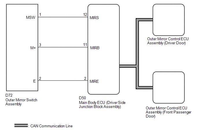
The main body ECU (driver side junction block assembly) detects the mirror adjust switch status and sends the signal to the outer mirror control ECU assembly via CAN communication. On receiving the signal, each outer mirror control ECU assembly operates the vertical and horizontal mirror motors to adjust the mirror surface position.
WIRING DIAGRAM
PROCEDURE
|
1. |
CHECK CAN COMMUNICATION SYSTEM |
(a) Use the Techstream to check if the CAN communication system is functioning
normally (See page .gif) ).
).
OK:
CAN communication DTC is not output.
| NG | .gif) |
GO TO CAN COMMUNICATION SYSTEM (DIAGNOSTIC TROUBLE CODE CHART) |
|
.gif)
|
2. |
READ VALUE USING TECHSTREAM (OUTER MIRROR SWITCH ASSEMBLY) |
(a) Connect the Techstream to the DLC3.
(b) Turn the ignition switch ON.
(c) Turn the Techstream on.
(d) Enter the following menus: Body Electrical / Main Body / Data List.
(e) Read the Data List according to the display on the Techstream.
Main Body|
Tester Display |
Measurement Item/Range |
Normal Condition |
Diagnostic Note |
|---|---|---|---|
|
Mirror Selection SW (R) |
Mirror select switch signal for RH mirror / ON or OFF |
ON: Mirror select switch in R position OFF: Mirror select switch off or in L position |
- |
|
Mirror Selection SW (L) |
Mirror select switch signal for LH mirror / ON or OFF |
ON: Mirror select switch in L position OFF: Mirror select switch off or in R position |
- |
|
Mirror Position SW (R) |
Mirror adjust switch signal (Right) / ON or OFF |
ON: Mirror adjust switch pressed right OFF: Mirror adjust switch not pressed right |
Check with the mirror select switch in any position except neutral |
|
Mirror Position SW (L) |
Mirror adjust switch signal (Left) / ON or OFF |
ON: Mirror adjust switch pressed left OFF: Mirror adjust switch not pressed left |
Check with the mirror select switch in any position except neutral |
|
Mirror Position SW (Up) |
Mirror adjust switch signal (Up) / ON or OFF |
ON: Mirror adjust switch pressed up OFF: Mirror adjust switch not pressed up |
Check with the mirror select switch in any position except neutral |
|
Mirror Position SW (Dwn) |
Mirror adjust switch signal (Down) / ON or OFF |
ON: Mirror adjust switch pressed down OFF: Mirror adjust switch not pressed down |
Check with the mirror select switch in any position except neutral |
OK:
On the Techstream screen, ON or OFF is displayed for each item according to the table above.
| OK | |
REPLACE MAIN BODY ECU (DRIVER SIDE JUNCTION BLOCK ASSEMBLY) |
|
|
3. |
INSPECT OUTER MIRROR SWITCH ASSEMBLY |
|
(a) Remove the outer mirror switch assembly (See page
|
|
(b) Measure the resistance according to the value(s) in the table below.
Standard Resistance:
|
Tester Connection |
Condition |
Specified Condition |
|---|---|---|
|
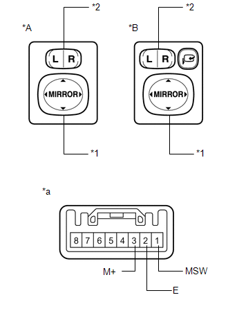
3 (M+) - 2 (E) |
Mirror adjust switch pressed up* |
90 to 110 Ω |
|
Mirror adjust switch pressed down* |
437 to 503 Ω |
|
|
Mirror adjust switch pressed left* |
744 to 856 Ω |
|
|
Mirror adjust switch pressed right* |
225 to 275 Ω |
|
|
1 (MSW) - 2 (E) |
Mirror select switch R |
Below 10 Ω |
|
Mirror select switch L |
90 to 110 Ω |
|
|
Mirror select switch off |
10 kΩ or higher |
- *: Set the mirror select switch to L or R.
|
*A |
w/o Retract Mirror |
|
*B |
w/ Retract Mirror |
|
*1 |
Mirror Adjust Switch |
|
*2 |
Mirror Select Switch |
|
*a |
Component without harness connected (Outer Mirror Switch Assembly) |
| NG | |
REPLACE OUTER MIRROR SWITCH ASSEMBLY |
|
|
4. |
CHECK HARNESS AND CONNECTOR (OUTER MIRROR SWITCH - MAIN BODY ECU (DRIVER SIDE JUNCTION BLOCK ASSEMBLY)) |
(a) Disconnect the D72 connector from the outer mirror switch assembly.
(b) Disconnect the D50 connector from the main body ECU (driver side junction block assembly).
(c) Measure the resistance according to the value(s) in the table below.
Standard Resistance:
|
Tester Connection |
Condition |
Specified Condition |
|---|---|---|
|
D72-2 (E) - D50-2 (MIRE) |
Always |
Below 1 Ω |
|
D72-3 (M+) - D50-11 (MIRB) |
Always |
Below 1 Ω |
|
D72-1 (MSW) - D50-12 (MIRS) |
Always |
Below 1 Ω |
|
D72-2 (E) - Body ground |
Always |
10 kΩ or higher |
|
D72-3 (M+) - Body ground |
Always |
10 kΩ or higher |
|
D72-1 (MSW) - Body ground |
Always |
10 kΩ or higher |
| OK | |
REPLACE MAIN BODY ECU (DRIVER SIDE JUNCTION BLOCK ASSEMBLY) |
| NG | |
REPAIR OR REPLACE HARNESS OR CONNECTOR |
 Front Passenger Side Power Mirror cannot be Adjusted with Power Mirror Switch
SYSTEM DESCRIPTION
When the mirror adjust switch is operated, the main body ECU (driver side junction
block assembly) detects the switch operation and sends the mirror adjust switch
signal to the ...
 Power Mirror Surface Position is not Memorized
SYSTEM DESCRIPTION
If either the M1 or M2 seat memory switch is pressed, the outer mirror control
ECU assembly (driver door) detects the switch operation and sends the seat memory
switch signal t ...
Other materials about Toyota Venza:
Installation
INSTALLATION
PROCEDURE
1. INSTALL FUEL PRESSURE REGULATOR ASSEMBLY
(a) Apply a light coat of gasoline to 2 new O-rings, and install them
onto the fuel pressure regulator.
Text in Illustration
*1
New O-r ...
Components
COMPONENTS
ILLUSTRATION
ILLUSTRATION
ILLUSTRATION
ILLUSTRATION
ILLUSTRATION
ILLUSTRATION
ILLUSTRATION
...
How To Proceed With Troubleshooting
CAUTION / NOTICE / HINT
HINT:
Use the following procedure to troubleshoot.
PROCEDURE
1.
VEHICLE BROUGHT TO WORKSHOP
NEXT
2.
CUSTOMER PR ...

0.1653