Toyota Venza: Installation
INSTALLATION
PROCEDURE
1. REPAIR INSTRUCTION
.gif)
2. INSTALL REAR DOOR LOWER OUTSIDE STRIPE
(a) Refer to the illustration to position the rear door lower outside stripe.
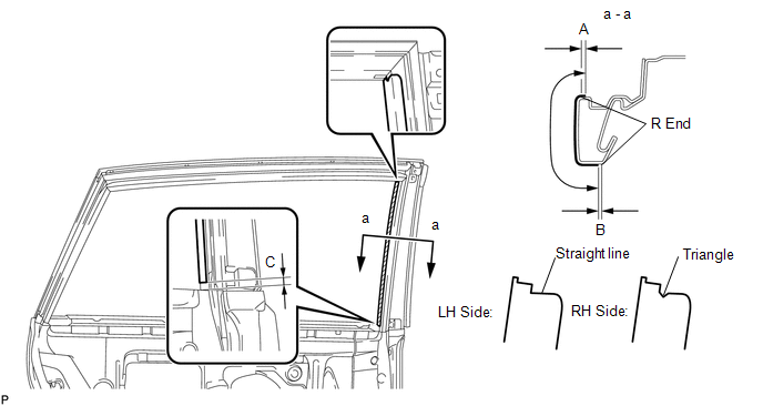 Standard Measurement
|
Dimension |
Measurement |
|---|---|
|
A |
+1.5 mm (+0.0591 in.) |
|
B |
-1.0 mm (-0.0394 in.) |
|
C |
7.5 mm (0.295 in.) |
(b) Remove the release paper and apply the stripe.
3. INSTALL NO. 2 BLACK OUT TAPE
(a) Refer to the illustration to position the No. 2 black out tape.
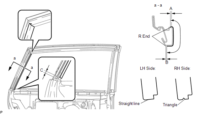 Standard Measurement
|
Dimension |
Measurement |
|---|---|
|
A |
+1.5 mm (+0.0591 in.) |
|
B |
-1.0 mm (-0.0394 in.) |
|
C |
5.0 mm (0.197 in.) |
(b) Remove the release paper and apply the tape.
4. INSTALL REAR DOOR OUTSIDE STRIPE
(a) Refer to the illustration to position the rear door outside stripe.
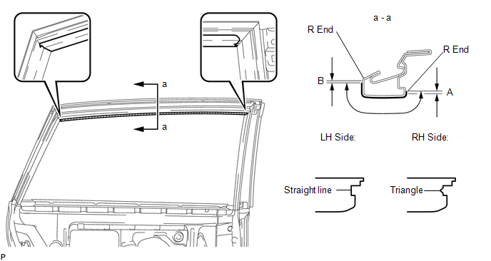 Standard Measurement
|
Dimension |
Measurement |
|---|---|
|
A |
+1.5 mm (+0.0591 in.) |
|
B |
-1.0 mm (-0.0394 in.) |
(b) Remove the release paper and apply the stripe.
5. INSTALL REAR DOOR GLASS SUB-ASSEMBLY
6. INSTALL REAR DOOR WINDOW DIVISION BAR SUB-ASSEMBLY
7. INSTALL REAR DOOR GLASS RUN
8. INSTALL REAR DOOR WEATHERSTRIP
9. INSTALL REAR DOOR CHECK ASSEMBLY
10. INSTALL REAR DOOR SERVICE HOLE COVER
11. INSTALL REAR DOOR FRAME GARNISH
12. INSTALL REAR DOOR INSIDE HANDLE SUB-ASSEMBLY
13. INSTALL REAR DOOR TRIM BOARD SUB-ASSEMBLY
14. INSTALL REAR POWER WINDOW REGULATOR SWITCH ASSEMBLY WITH REAR DOOR ARMREST BASE PANEL
15. INSTALL REAR DOOR INSIDE HANDLE BEZEL PLUG
16. CONNECT CABLE TO NEGATIVE BATTERY TERMINAL
NOTICE:
When disconnecting the cable, some systems need to be initialized after the cable
is reconnected (See page ).
17. INITIALIZE POWER WINDOW CONTROL SYSTEM
(See page )
 Removal
REMOVAL
PROCEDURE
1. DISCONNECT CABLE FROM NEGATIVE BATTERY TERMINAL
NOTICE:
When disconnecting the cable, some systems need to be initialized after the cable
is reconnected (See page ).
2. RE ...
 Front Bumper
...
Other materials about Toyota Venza:
Washer Nozzle(for Rear Side)
Components
COMPONENTS
ILLUSTRATION
On-vehicle Inspection
ON-VEHICLE INSPECTION
PROCEDURE
1. INSPECT REAR WASHER NOZZLE
(a) With the engine running, check where the washer fluid hits the windshield.
Standard Measurement
Area
...
Door Control Transmitter(w/o Smart Key System)
Components
COMPONENTS
ILLUSTRATION
Removal
REMOVAL
PROCEDURE
1. REMOVE TRANSMITTER HOUSING COVER
2. REMOVE DOOR CONTROL TRANSMITTER MODULE
Inspection
INSPECTION
PROCEDURE
1. INSPECT DOOR CONTROL TRANSMITTER
(a) Inspect operation of th ...
Customize Parameters
CUSTOMIZE PARAMETERS
1. CUSTOMIZING FUNCTION WITH TECHSTREAM
HINT:
The following items can be customized.
NOTICE:
When the customer requests a change in a function, first make sure that
the function can be customized.
Be sure to make a not ...

0.1325