Toyota Venza: Engine compartment
 General maintenance
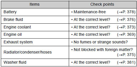
Listed below are the general maintenance items that should be performed at
the intervals specified in the “Scheduled Maintenance Guide”, “Owner’s Manual Supplement”.
It is recommended th ...
 Vehicle interior
...
Other materials about Toyota Venza:
On-vehicle Inspection
ON-VEHICLE INSPECTION
PROCEDURE
1. INSPECT COOLER CONDENSER ASSEMBLY
(a) If the cooler condenser assembly fins are dirty, clean them with water and
dry with compressed air.
NOTICE:
Do not damage the cooler condenser assembly fins.
(b) If any cooler con ...
Installation
INSTALLATION
CAUTION / NOTICE / HINT
HINT:
Perform "Inspection After Repair" after replacing the engine assembly (See page
).
PROCEDURE
1. INSTALL ENGINE HANGERS
2. REMOVE ENGINE STAND
(a) Remove the engine stand.
3. INSTALL ENGINE WIRE
...
Torque Sensor Circuit Malfunction (C1511-C1514,C1517)
DESCRIPTION
The torque sensor converts the rotation torque input to the steering wheel into
an electrical signal and sends it to the power steering ECU. Based on this signal,
the ECU detects steering effort.
DTC No.
DTC Detection Co ...

0.138