Toyota Venza: Components
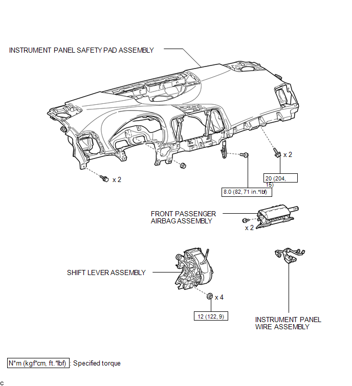
COMPONENTS
ILLUSTRATION

 On-vehicle Inspection
ON-VEHICLE INSPECTION
CAUTION / NOTICE / HINT
CAUTION:
Be sure to correctly follow the removal and installation procedures for the front
passenger airbag assembly.
PROCEDURE
1. INSPECT FRONT PA ...
Other materials about Toyota Venza:
Reassembly
REASSEMBLY
PROCEDURE
1. INSTALL NO. 1 REAR BUMPER REINFORCEMENT
(a) Install the No. 1 rear bumper reinforcement with the 6 nuts.
Torque:
68 N·m {693 kgf·cm, 50 ft·lbf}
2. INSTALL REAR BUMP ...
Removal
REMOVAL
PROCEDURE
1. REMOVE ENGINE ASSEMBLY WITH TRANSAXLE
(a) Remove the engine and transaxle (See page
).
2. REMOVE EXHAUST MANIFOLD CONVERTER SUB-ASSEMBLY
(a) Remove the exhaust manifold converter (See page
).
3. REMOVE THROTTLE BODY ASSEMBLY
...
No Answer-Back
DESCRIPTION
In some cases, wireless door lock control functions are normal but the hazard
warning light and/or wireless door lock buzzer answer-back function(s) does not
operate. In such cases, the main body ECU (driver side junction block assembly)
haz ...

0.1728