Toyota Venza: Components
COMPONENTS
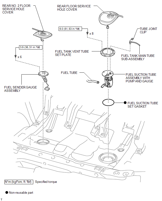
ILLUSTRATION
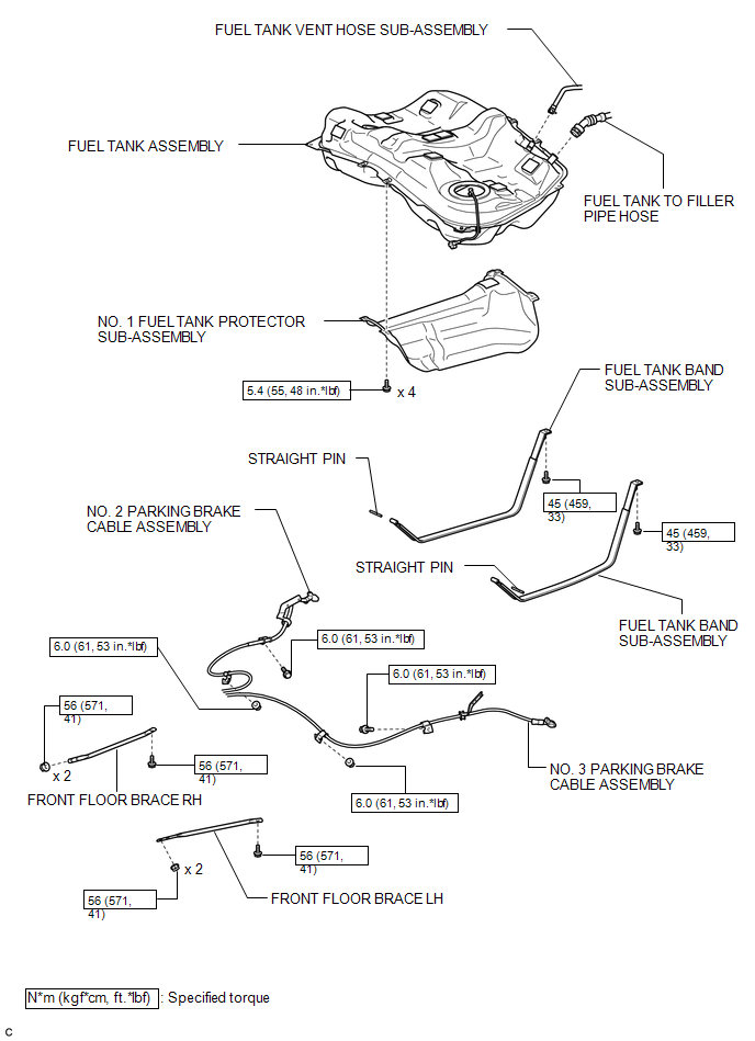
ILLUSTRATION
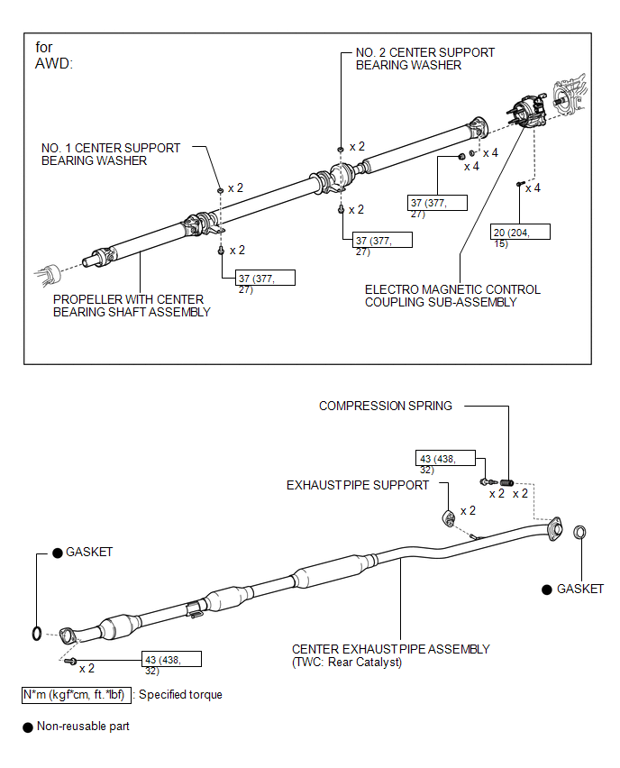
ILLUSTRATION
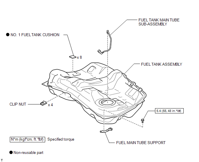
ILLUSTRATION
 Fuel Tank
...
 Removal
REMOVAL
PROCEDURE
1. DISCHARGE FUEL SYSTEM PRESSURE
HINT:
(See page ).
2. DISCONNECT CABLE FROM NEGATIVE BATTERY TERMINAL
NOTICE:
When disconnecting the cable, some systems need to be initiali ...
Other materials about Toyota Venza:
Short in Curtain Shield Squib LH Circuit (B1835/58-B1838/58)
DESCRIPTION
The curtain shield squib LH circuit consists of the center airbag sensor assembly
and curtain shield airbag assembly LH.
The center airbag sensor assembly uses this circuit to deploy the airbag when
deployment conditions are met.
These DTCs ...
One or more Power Seat Motors do not Operate
DESCRIPTION
Signals are input into the position control ECU and switch assembly. The built-in
ECU manages the signals received from the position control ECU and switch assembly,
and operates each motor. If the position control ECU and switch assembly rece ...
Dtc Check / Clear
DTC CHECK / CLEAR
1. DTC CHECK/CLEAR (USING TECHSTREAM)
(a) CHECK DTC
(1) Connect the Techstream to the DLC3.
(2) Turn the ignition switch on (IG).
(3) Read the DTC by following the prompts on the Techstream screen.
HINT:
Refer to the Techstream operato ...

0.132