Toyota Venza: Combination Meter
Components
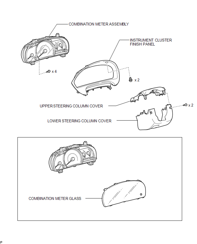
COMPONENTS
ILLUSTRATION
Disassembly
DISASSEMBLY
PROCEDURE
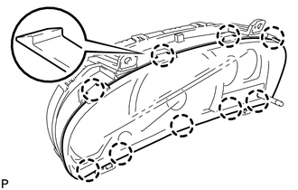
1. REMOVE COMBINATION METER GLASS
|
(a) Disengage the 9 claws to remove the combination meter glass. |
|
Removal
REMOVAL
PROCEDURE
1. REMOVE LOWER STEERING COLUMN COVER
.gif)
2. REMOVE UPPER STEERING COLUMN COVER
3. DISCONNECT CABLE FROM NEGATIVE BATTERY TERMINAL
NOTICE:
When disconnecting the cable, some systems need to be initialized after the cable
is reconnected (See page ).
4. REMOVE INSTRUMENT CLUSTER FINISH PANEL
|
(a) Remove the 2 clips. |
|
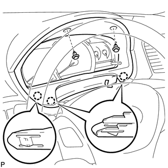
(b) Disengage the 3 claws and remove the instrument cluster finish panel.
5. REMOVE COMBINATION METER ASSEMBLY
|
(a) Remove the 4 screws. |
|
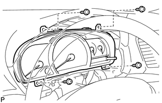
(b) Disconnect the connectors and remove the combination meter assembly.
Reassembly
REASSEMBLY
PROCEDURE
1. INSTALL COMBINATION METER GLASS
|
(a) Engage the 9 claws to install the combination meter glass. |
|
.png)
Installation
INSTALLATION
PROCEDURE
1. INSTALL COMBINATION METER ASSEMBLY
|
(a) Connect the connectors. |
|
.png)
(b) Install the combination meter assembly with the 4 screws.
2. INSTALL INSTRUMENT CLUSTER FINISH PANEL
|
(a) Engage the 3 claws. |
|
.png)
(b) Install the instrument cluster finish panel with the 2 clips.
3. CONNECT CABLE TO NEGATIVE BATTERY TERMINAL
NOTICE:
When disconnecting the cable, some systems need to be initialized after the cable
is reconnected (See page .gif) ).
).
4. INSTALL UPPER STEERING COLUMN COVER
5. INSTALL LOWER STEERING COLUMN COVER
 Problem Symptoms Table
PROBLEM SYMPTOMS TABLE
HINT:
Use the table below to help determine the cause of problem symptoms. If multiple
suspected areas are listed, the potential causes of the symptoms are listed in order
...

Other materials about Toyota Venza:
Horn System
Precaution
PRECAUTION
NOTICE:
When disconnecting the cable from the negative (-) battery terminal, initialize
the following system after the cable is reconnected.
System Name
See Procedure
Back Door Closer System
...
Installation
INSTALLATION
PROCEDURE
1. INSTALL COOLER CONDENSER ASSEMBLY
(a) Install the cooler condenser assembly with the 4 bolts.
Torque:
6.0 N·m {61 kgf·cm, 53 in·lbf}
HINT:
If the condenser is replaced with a new one, add compressor oil t ...
All Door Entry Lock/Unlock Functions and Wireless Functions do not Operate
DESCRIPTION
When the entry door lock and unlock functions and wireless door lock and unlock
functions do not operate, radio wave interference, or a malfunction in the key or
signal circuit between the door control receiver assembly and certification ECU
...

0.1234