Toyota Venza: All Door Entry Lock/Unlock Functions do not Operate, but Wireless Functions Operate
DESCRIPTION
When the wireless door lock and unlock functions operate, the communication circuit between the door lock receiver assembly and certification ECU (smart key ECU assembly) is normal. When the entry lock and unlock functions do not operate, radio wave interference, a customized entry cancel function, or a communication error between the key and vehicle in the smart communication circuit, is suspected.
CAUTION / NOTICE / HINT
NOTICE:
- The smart key system (for entry function) uses a multiplex communication
system (LIN communication system) and CAN communication system. Inspect
the communication function by following How to Proceed with Troubleshooting
(See page
.gif) ). Troubleshoot the smart
). Troubleshoot the smart
key system (for entry function) after confirming that the communication system is functioning properly. - Confirm that another key is not in the cabin.
PROCEDURE
|
1. |
CHECK POWER DOOR LOCK OPERATION |
(a) When the door control switch on the master switch assembly is operated, check
that the doors unlock and lock according to switch operation (See page
).
OK:
Door locks operate normally.
| NG | .gif) |
GO TO POWER DOOR LOCK CONTROL SYSTEM (Proceed to Problem Symptoms Table) |
|
.gif)
|
2. |
READ VALUE USING TECHSTREAM (ENTRY CANCEL FUNCTION) |
(a) Connect the Techstream to the DLC3.
(b) Turn the engine switch on (IG).
(c) Turn the Techstream on.
(d) Enter the following menus: Body Electrical / Smart Key / Data List.
(e) Read the Data List according to the display on the Techstream.
Smart Key (Certification ECU (Smart Key ECU Assembly))|
Tester Display |
Measurement Item/Range |
Normal Condition |
Diagnostic Note |
|---|---|---|---|
|
Auto Entry Cancel SW |
Entry function cancel / ON or OFF |
Mode status displayed |
- |
|
Result |
Proceed to |
|---|---|
|
Entry function cancel is off. |
A |
|
Entry function cancel is on. |
B |
| B | |
PERFORM CANCELLATION OF ENTRY KEY CANCEL FUNCTION |
|
|
3. |
CHECK WAVE ENVIRONMENT |
(a) Move the key as described below and perform the operation inspection.
HINT:
- When the key is brought near the door outside handle assembly or outside electrical key oscillator, the possibility of wave interference decreases, and it can be determined if wave interference is causing the problem symptom.
- The transmitting waves of the wireless functions and entry functions are the same, but the wave logic is different. Therefore, it is possible that only the wireless functions or only the entry functions are affected by wave interference.
|
(b) Bring the key near the driver door outside handle assembly, and perform a front driver door entry lock and unlock operation check. NOTICE: If the key is brought within 0.2 m (0.656 ft.) of the door outside handle assembly, communication is not possible. |
|
|
(c) Bring the key near the front passenger door outside handle assembly, and perform a front passenger door entry lock and unlock operation check. NOTICE: If the key is brought within 0.2 m (0.656 ft.) of the door outside handle assembly, communication is not possible. |
|
|
(d) Bring the key near the outside electrical key oscillator (for rear side), and perform an entry back door open function check. NOTICE: If the key is brought within 0.2 m (0.656 ft.) of the rear bumper, communication is not possible. HINT: If the inspection result indicates that the problem only occurs in certain locations or times of day, the possibility of wave interference is high. Also, added vehicle components may cause wave interference. If installed, remove them and perform the operation check. Result:
|
|
| B | |
AFFECTED BY WAVE INTERFERENCE |
| C | |
GO TO OTHER PROBLEM (Proceed to Problem Symptoms Table) |
|
|
4. |
PERFORM KEY DIAGNOSTIC MODE INSPECTION |
|
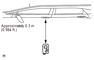
(a) Diagnostic mode inspection (door electrical key oscillator (for driver side)) (1) Connect the Techstream to the DLC3. (2) Turn the engine switch on (IG). (3) Turn the Techstream on. (4) Enter the following menus: Body Electrical / Smart Key / Key Communication Check / Overhead + Driver Side. (5) When the key is in the position shown in the illustration, check that the wireless door lock buzzer sounds. |
|
|
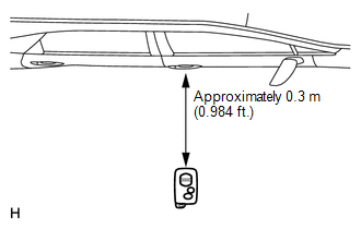
(b) Diagnostic mode inspection (door electrical key oscillator (for front passenger side)) (1) Connect the Techstream to the DLC3. (2) Turn the engine switch on (IG). (3) Turn the Techstream on. (4) Enter the following menus: Body Electrical / Smart Key / Key Communication Check / Overhead + Passenger Side. (5) When the key is in the position shown in the illustration, check that the wireless door lock buzzer sounds. |
|
|
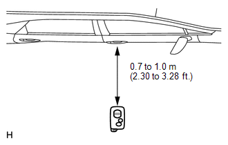
(c) Diagnostic mode inspection (indoor electrical key oscillator (for front floor)) (1) Connect the Techstream to the DLC3. (2) Turn the engine switch on (IG). (3) Turn the Techstream on. (4) Enter the following menus: Body Electrical / Smart Key / Key Communication Check / Overhead + Front Room. (5) When the key is in the position shown in the illustration, check that the wireless door lock buzzer sounds. |
|
.png)
|
(d) Diagnostic mode inspection (indoor electrical key oscillator (for center floor)) (1) Connect the Techstream to the DLC3. (2) Turn the engine switch on (IG). (3) Turn the Techstream on. (4) Enter the following menus: Body Electrical / Smart Key / Key Communication Check / Overhead + Rear Room. (5) When the key is in the position shown in the illustration, check that the wireless door lock buzzer sounds. |
|
.png)
|
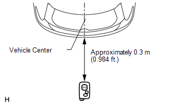
(e) Diagnostic mode inspection (indoor electrical key oscillator (for rear floor)) (1) Connect the Techstream to the DLC3. (2) Turn the engine switch on (IG). (3) Turn the Techstream on. (4) Enter the following menus: Body Electrical / Smart Key / Key Communication Check / Overhead + Back Door (inside). (5) When the key is held at the same height as the rear bumper upper surface and aligned with the center of the rear of the vehicle, check that the wireless door lock buzzer sounds. |
|
.png)
|
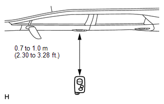
(f) Diagnostic mode inspection (outside electrical key oscillator (for rear side)) (1) Connect the Techstream to the DLC3. (2) Turn the engine switch on (IG). (3) Turn the Techstream on. (4) Enter the following menus: Body Electrical / Smart Key / Key Communication Check / Overhead + Back Door (outside). (5) When the key is in the position shown in the illustration, check that the wireless door lock buzzer sounds. Result:
|
|
.png)
| B | |
GO TO OTHER PROBLEM (Proceed to Problem Symptoms Table for Each Door) |
| C | |
GO TO OTHER PROBLEM (Proceed to Room Oscillator does not Recognize Key) |
| D | |
GO TO OTHER PROBLEM (Proceed to Problem Symptoms Table) |
| E | |
REPLACE CERTIFICATION ECU (SMART KEY ECU ASSEMBLY) |
|
|
5. |
CHECK ELECTRICAL KEY TRANSMITTER |
(a) Check if another registered key is available.
|
Result |
Proceed to |
|---|---|
|
Another registered key is not available. |
A |
|
Another registered key is available. |
B |
| B | |
GO TO STEP 7 |
|
|
6. |
REGISTER ELECTRICAL KEY TRANSMITTER |
(a) Register a new key (See page ).
|
|
7. |
CHECK ELECTRICAL KEY TRANSMITTER (OPERATION) |
(a) Using the key registered in the previous step or another registered key,
check that the entry function operates normally (See page
).
OK:
Entry function operates normally.
| OK | |
REPLACE ELECTRICAL KEY TRANSMITTER (REPLACE MALFUNCTIONING KEY) |
| NG | |
REPLACE CERTIFICATION ECU (SMART KEY ECU ASSEMBLY) |
 All Door Entry Lock/Unlock Functions and Wireless Functions do not Operate
DESCRIPTION
When the entry door lock and unlock functions and wireless door lock and unlock
functions do not operate, radio wave interference, or a malfunction in the key or
signal circuit betwee ...
 Driver Side Door Entry Unlock Function does not Operate
DESCRIPTION
If the driver door entry lock function operates normally, but its entry unlock
function does not, this means that the request code from the driver door is being
output normally. In th ...
Other materials about Toyota Venza:
Removal
REMOVAL
PROCEDURE
1. REMOVE REAR WHEELS
2. SEPARATE REAR STABILIZER LINK ASSEMBLY LH
(a) Remove the nut and separate the rear stabilizer link assembly LH
from the rear stabilizer bar.
Text in Illustration
*1
...
System Description
SYSTEM DESCRIPTION
1. WIRELESS DOOR LOCK CONTROL SYSTEM
The wireless door lock control system can be used to lock and unlock all doors
from a distance. The system is controlled by a door control transmitter which sends
radio waves to the door control rec ...
Precaution
PRECAUTION
1. NOTICE FOR INITIALIZATION
NOTICE:
When disconnecting the cable from the negative (-) battery terminal, initialize
the following system after the cable is reconnected.
System Name
See Procedure
Back Doo ...

0.1352