Toyota Venza: Wireless Door Lock Tuner Circuit Malfunction (B1242)
DESCRIPTION
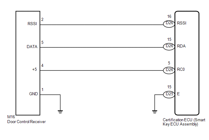
The door control receiver is used to receive electrical waves relating to the entry functions of the smart key system. The certification ECU (smart key ECU assembly) decodes the requested smart key system operation by identifying a key code based on the radio waves received via the door control receiver. The door control receiver receives a signal from the door control transmitter and sends signals to the main body ECU (driver side junction block assembly) through the certification ECU (smart key ECU assembly). The certification ECU (smart key ECU assembly) then sends a command, according to the requested operation, to each ECU (ex. if door lock operation is requested, the certification ECU (smart key ECU assembly) sends a door lock command to the main body ECU (driver side junction block assembly)).
|
DTC No. |
DTC Detection Condition |
Trouble Area |
|---|---|---|
|
B1242 |
|
|
WIRING DIAGRAM
CAUTION / NOTICE / HINT
NOTICE:
- When replacing or inspecting the door control receiver and wire harness, do not change the position or length of the wire harness. If the wire harness is too close to the door control receiver, entry and wireless function performance may be affected.
- Before performing the inspection, check that there are no problems related to the CAN communication system and LIN communication system.
PROCEDURE
|
1. |
CHECK HARNESS AND CONNECTOR (DOOR CONTROL RECEIVER - CERTIFICATION ECU AND BODY GROUND) |
(a) Disconnect the D25 and D26 certification ECU (smart key ECU assembly) connectors.
(b) Disconnect the M16 door control receiver connector.
(c) Measure the resistance according to the value(s) in the table below.
Standard Resistance:
|
Tester Connection |
Condition |
Specified Condition |
|---|---|---|
|
D26-16 (RSSI) - M16-2 (RSSI) |
Always |
Below 1 Ω |
|
D26-15 (RDA) - M16-5 (DATA) |
Always |
Below 1 Ω |
|
D26-5 (RC0) - M16-4 (+5) |
Always |
Below 1 Ω |
|
D25-15 (E) - Body ground |
Always |
Below 1 Ω |
|
M16-1 (GND) - Body ground |
Always |
Below 1 Ω |
|
D26-16 (RSSI) or M16-2 (RSSI) - Body ground |
Always |
10 kΩ or higher |
|
D26-15 (RDA) or M16-5 (DATA) - Body ground |
Always |
10 kΩ or higher |
|
D26-5 (RC0) or M16-4 (+5) - Body ground |
Always |
10 kΩ or higher |
|
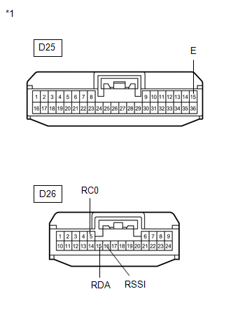
*1 |
Front view of wire harness connector (to Certification ECU (Smart Key ECU Assembly)) |
|
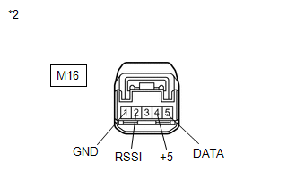
*2 |
Front view of wire harness connector (to Door Control Receiver) |
| NG | .gif) |
REPAIR OR REPLACE HARNESS OR CONNECTOR |
|
.gif)
|
2. |
CHECK CERTIFICATION ECU (SMART KEY ECU ASSEMBLY) |
|
(a) Reconnect the D25 and D26 certification ECU (smart key ECU assembly) connectors. |
|
(b) Measure the voltage according to the value(s) in the table below.
Standard Voltage:
|
Tester Connection |
Condition |
Specified Condition |
|---|---|---|
|
D26-5 (RC0) - D25-15 (E) |
Engine switch off, all doors closed and transmitter switch pressed |
4.5 to 5.5 V |
|
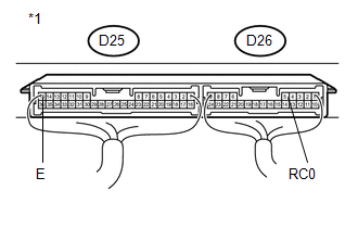
*1 |
Component with harness connected (Certification ECU (Smart Key ECU Assembly)) |
| NG | |
REPLACE CERTIFICATION ECU (SMART KEY ECU ASSEMBLY) |
|
|
3. |
REPLACE DOOR CONTROL RECEIVER |
(a) Temporarily replace the door control receiver with a new one (See page
.gif) ).
).
|
|
4. |
CHECK FOR DTC |
(a) Clear the DTC (See page ).
(b) Recheck for DTCs.
OK:
DTC B1242 is not output.
| OK | |
END (DOOR CONTROL RECEIVER WAS DEFECTIVE) |
| NG | |
REPLACE CERTIFICATION ECU (SMART KEY ECU ASSEMBLY) |
 Diagnostic Trouble Code Chart
DIAGNOSTIC TROUBLE CODE CHART
HINT:
If a trouble code is output during the DTC check, inspect the trouble areas listed
for that code. For details of the code, refer to "See page" in the ...
 No Answer-Back
DESCRIPTION
In some cases, wireless door lock control functions are normal but the hazard
warning light and/or wireless door lock buzzer answer-back function(s) does not
operate. In such cases, t ...
Other materials about Toyota Venza:
Inspection
INSPECTION
PROCEDURE
1. INSPECT ATF TEMPERATURE SENSOR ASSEMBLY
(a) Measure the resistance according to the value(s) in the table below.
Standard Resistance:
Tester Connection
Condition
Sp ...
Lost Communication with ECM / PCM "A" (U0100)
DESCRIPTION
The engine control unit communicates with the TCM using the Controller Area Network
(CAN).
If there is a problem in this communication, the TCM sets a DTC.
DTC No.
DTC Detection Condition
Trouble Area
...
Brake Warning Light Remains ON
DESCRIPTION
The skid control ECU is connected to the combination meter via CAN communication.
If any of the following is detected, the brake warning light remains on:
The skid control ECU connector is disconnected from the skid control
ECU.
T ...

0.1512