Toyota Venza: Window Glass Antenna Wire
On-vehicle Inspection
ON-VEHICLE INSPECTION
PROCEDURE
1. INSPECT WINDOW GLASS ANTENNA WIRE
|
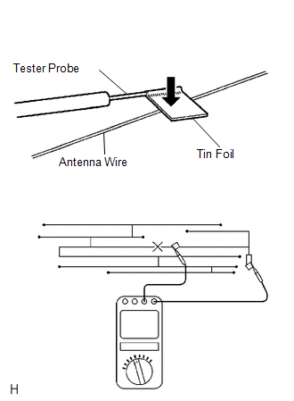
(a) Check for continuity of the antenna. HINT: Check for continuity at the center of each antenna wire as shown in the illustration. NOTICE:
OK: There is continuity in the antenna. If the result is not as specified, repair the window glass antenna wire. |
|
Repair
REPAIR
PROCEDURE
1. REPAIR WINDOW GLASS ANTENNA WIRE
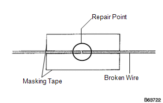
(a) Clean the broken wire tips with a grease, wax and silicone remover.
(b) Place masking tape along both sides of the wire to be repaired.
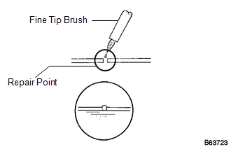
(c) Thoroughly mix the repair agent (Dupont paste No. 4817 or equivalent).
|
(d) Using a fine tip brush, apply a small amount of the repair agent to the wire. |
|
(e) After a few minutes, remove the masking tape.
NOTICE:
Do not repair the antenna wire again for at least 24 hours.
 Stereo Jack Adapter Assembly
Components
COMPONENTS
ILLUSTRATION
Removal
REMOVAL
PROCEDURE
1. REMOVE UPPER CONSOLE PANEL SUB-ASSEMBLY (w/o Seat Heater System)
2. REMOVE UPPER CONSOLE PANEL SUB-ASSEMBLY (w/ Seat Hea ...

Other materials about Toyota Venza:
Bottle holders
► For front seats
► For rear seats
NOTICE
- Items that should not be stowed in the bottle holders
Put the cap on before stowing a bottle. Do not place open bottles in the bottle
holders, or glasses and paper cups containing liquid. ...
Camshaft Position "B" Actuator Circuit / Open (Bank 1) (P0013)
DESCRIPTION
The Variable Valve Timing (VVT) system adjusts the exhaust valve timing to improve
driveability. The engine oil pressure turns the VVT controller to adjust the valve
timing.
The camshaft timing oil control valve is a solenoid valve and switch ...
Inspection
INSPECTION
PROCEDURE
1. INSPECT PAD LINING THICKNESS
(a) Using a ruler, measure the pad lining thickness.
Text in Illustration
*1
Ruler
Standard thickness of a new pad:
10.0 mm (0.394 ...

0.1799