Toyota Venza: Vehicle Speed Sensor "A" Intermittent / Erratic / High (P0503)
DESCRIPTION
If a malfunction (a rapid change in vehicle speed) in the vehicle speed signal being output from the skid control ECU is detected while the cruise control is in operation, the ECM determines that there is a momentary interruption or noise, and outputs a DTC.
|
DTC |
DTC Detection Condition |
Trouble Area |
|---|---|---|
|
P0503 |
A momentary interruption and noise are detected when a rapid change of the vehicle speed occurs while cruise control is in operation. |
|
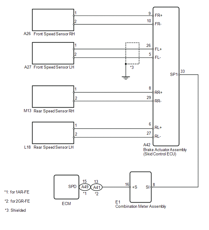
WIRING DIAGRAM
CAUTION / NOTICE / HINT
This DTC may be output by the vehicle stability control system at the same time. In that case, perform troubleshooting for the vehicle stability control system first.
PROCEDURE
|
1. |
CHECK DTC (VEHICLE STABILITY CONTROL SYSTEM) |
(a) Connect the Techstream to the DLC3.
(b) Turn the ignition switch to ON.
(c) Turn the Techstream on.
(d) Enter the following menus: Chassis / ABS/VSC/TRC / DTC.
(e) Check for DTCs.
|
Result |
Proceed to |
|---|---|
|
DTC is not output |
A |
|
DTC is output |
B |
| B | .gif) |
GO TO VEHICLE STABILITY CONTROL SYSTEM (DTC CHART) |
|
.gif)
|
2. |
REPLACE COMBINATION METER ASSEMBLY |
(a) Replace the combination meter assembly (See page
.gif) ).
).
|
|
3. |
CHECK DTC (CRUISE CONTROL SYSTEM) |
(a) Clear the DTCs (See page ).
(b) Perform the following to make sure that the DTC detection conditions are met.
HINT:
If the detection conditions are not met, the malfunction cannot be detected.
(1) Drive at the required speed of between 40 km/h (25 mph) and 200 km/h (125 mph).
(2) Turn the cruise control main switch on.
(3) Push the -SET switch to activate the cruise control.
(c) Check for DTCs (See page ).
|
Result |
Proceed to |
|---|---|
|
DTC is not output |
A |
|
DTC P0503 is output (for 1AR-FE) |
B |
|
DTC P0503 is output (for 2GR-FE) |
C |
| A | |
END |
| B | |
REPLACE ECM |
| C | |
REPLACE ECM |
 Diagnostic Trouble Code Chart
DIAGNOSTIC TROUBLE CODE CHART
If a trouble code is displayed during the DTC check, check the trouble areas
listed for that code in the table below and proceed to the appropriate page.
Cruise Contr ...
 Vehicle Speed Sensor Malfunction (P0500)
DESCRIPTION
The vehicle speed sensors detect the wheel speed and send the appropriate signals
to the skid control ECU. The skid control ECU converts these wheel speed signals
into a 4-pulse signa ...
Other materials about Toyota Venza:
Front Occupant Classification Sensor LH Collision Detection (B1785)
DESCRIPTION
DTC B1785 is output when the occupant classification ECU receives a collision
detection signal sent by the front occupant classification sensor LH if an accident
occurs.
DTC B1785 is also output when the front seat assembly RH is subjected to ...
LVDS Signal Malfunction (from Extension Module) (B1532)
DESCRIPTION
The stereo component tuner assembly and the navigation receiver assembly are
connected by the LVDS communication line.
This DTC is stored when an LVDS communication error occurs between the stereo
component tuner assembly and the navigation r ...
Precaution
PRECAUTION
1. PRECAUTION FOR VEHICLE WITH SRS AIRBAG AND SEAT BELT PRETENSIONER
(a) Some operations in this section may affect the SRS airbags. Prior to performing
the corresponding operations, read the precautions regarding the SRS airbags (See
page ). ...

0.1456