
Toyota Venza: Vanity mirror
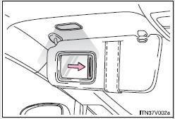
Slide the cover.
The light turns on when the cover is opened.
 Sun visors
1. Forward position:
Flip down.
2. Side position:
Flip down, unhook, and swing to the side. ...
 Power outlets
The power outlets can be used for 12V accessories that run on less than 10A.
►Console box
►Front passenger’s side instrument panel
►Luggage compartment
- The power ...
Other materials about Toyota Venza:
Components
COMPONENTS
ILLUSTRATION
ILLUSTRATION
ILLUSTRATION
ILLUSTRATION
ILLUSTRATION
...
On-vehicle Inspection
ON-VEHICLE INSPECTION
PROCEDURE
1. INSPECT DISCHARGE HEADLIGHT BULB
NOTICE:
Confirm the following items before replacing a discharge headlight bulb. If a
malfunction is discovered and repaired, perform the inspection again to confirm
the repair.
...
System Description
SYSTEM DESCRIPTION
1. CRUISE CONTROL SYSTEM
This system is controlled by the ECM, and is activated by the throttle position
sensor and motor. The ECM controls the following functions: ON-OFF, - SET, + RES,
CANCEL, vehicle speed control, motor output cont ...
© 2016-2026 Copyright www.tovenza.com

0.1309
0.1309