Toyota Venza: Lost Communication with Front Airbag Sensor RH (B1612/83,B1613/83)
DESCRIPTION
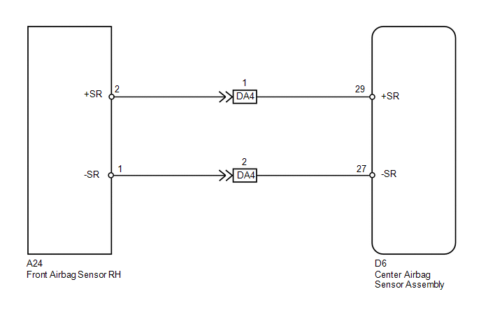
The front airbag sensor RH circuit consists of the center airbag sensor assembly and front airbag sensor RH.
The front airbag sensor RH detects impacts to the vehicle and sends signals to the center airbag sensor assembly to determine if the airbag should be deployed.
These DTCs are stored when a malfunction is detected in the front airbag sensor RH circuit.
|
DTC No. |
DTC Detection Condition |
Trouble Area |
|---|---|---|
|
B1612/83 B1613/83 |
|
|
WIRING DIAGRAM
PROCEDURE
|
1. |
CHECK CONNECTORS |
(a) Turn the ignition switch off.
(b) Disconnect the cable from the negative (-) battery terminal, and wait for at least 90 seconds.
(c) Check that the connectors are properly connected to the center airbag sensor assembly and front airbag sensor RH. Also check that the connectors that link the engine room main wire and instrument panel wire are properly connected.
OK:
The connectors are properly connected.
HINT:
If the connectors are not connected securely, reconnect the connectors and proceed to the next inspection.
(d) Disconnect the connectors from the center airbag sensor assembly and front airbag sensor RH. Also disconnect the connectors that link the engine room main wire and instrument panel wire.
(e) Check that the connector terminals are not damaged.
OK:
The terminals are not deformed or damaged.
| NG | .gif) |
REPLACE WIRE HARNESS |
|
.gif)
|
2. |
CHECK FRONT AIRBAG SENSOR RH CIRCUIT (OPEN) |
(a) Connect the connectors that link the engine room main wire and instrument panel wire.
(b) Using SST, connect terminals 29 (+SR) and 27 (-SR) of connector B.
NOTICE:
Do not forcibly insert SST into the terminals of the connector when connecting.
SST: 09843-18040
(c) Measure the resistance according to the value(s) in the table below.
Standard Resistance:
|
Tester Connection |
Condition |
Specified Condition |
|---|---|---|
|
A24-2 (+SR) - A24-1 (-SR) |
Always |
Below 1 Ω |
|
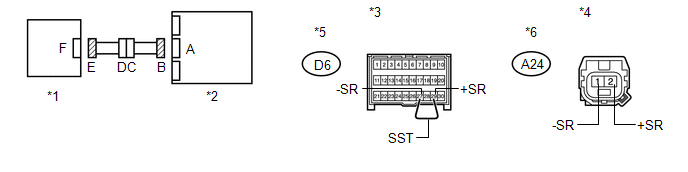
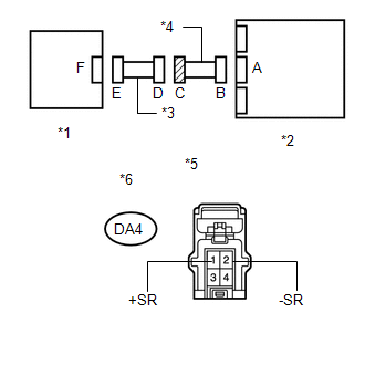
*1 |
Front Airbag Sensor RH |
*2 |
Center Airbag Sensor Assembly |
|
*3 |
Front view of wire harness connector (to Center Airbag Sensor Assembly) |
*4 |
Front view of wire harness connector (to Front Airbag Sensor RH) |
|
*5 |
Connector B |
*6 |
Connector E |
| NG | |
GO TO STEP 7 |
|
|
3. |
CHECK FRONT AIRBAG SENSOR RH CIRCUIT (SHORT) |
|
(a) Disconnect SST from connector B. |
|
(b) Measure the resistance according to the value(s) in the table below.
Standard Resistance:
|
Tester Connection |
Condition |
Specified Condition |
|---|---|---|
|
A24-2 (+SR) - A24-1 (-SR) |
Always |
1 MΩ or higher |
|
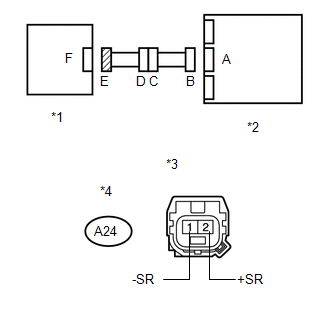
*1 |
Front Airbag Sensor RH |
|
*2 |
Center Airbag Sensor Assembly |
|
*3 |
Front view of wire harness connector (to Front Airbag Sensor RH) |
|
*4 |
Connector E |
| NG | |
GO TO STEP 8 |
|
|
4. |
CHECK FRONT AIRBAG SENSOR RH CIRCUIT (SHORT TO B+) |
|
(a) Connect the cable to the negative (-) battery terminal. |
|
(b) Turn the ignition switch to ON.
(c) Measure the voltage according to the value(s) in the table below.
Standard Voltage:
|
Tester Connection |
Switch Condition |
Specified Condition |
|---|---|---|
|
A24-2 (+SR) - Body ground |
Ignition switch ON |
Below 1 V |
|
A24-1 (-SR) - Body ground |
Ignition switch ON |
Below 1 V |
|
*1 |
Front Airbag Sensor RH |
|
*2 |
Center Airbag Sensor Assembly |
|
*3 |
Front view of wire harness connector (to Front Airbag Sensor RH) |
|
*4 |
Connector E |
| NG | |
GO TO STEP 9 |
|
|
5. |
CHECK FRONT AIRBAG SENSOR RH CIRCUIT (SHORT TO GROUND) |
|
(a) Turn the ignition switch off. |
|
(b) Disconnect the cable from the negative (-) battery terminal, and wait for at least 90 seconds.
(c) Measure the resistance according to the value(s) in the table below.
Standard Resistance:
|
Tester Connection |
Condition |
Specified Condition |
|---|---|---|
|
A24-2 (+SR) - Body ground |
Always |
1 MΩ or higher |
|
A24-1 (-SR) - Body ground |
Always |
1 MΩ or higher |
|
*1 |
Front Airbag Sensor RH |
|
*2 |
Center Airbag Sensor Assembly |
|
*3 |
Front view of wire harness connector (to Front Airbag Sensor RH) |
|
*4 |
Connector E |
| NG | |
GO TO STEP 10 |
|
|
6. |
CHECK FRONT AIRBAG SENSOR RH |
|
(a) Connect the connector to the center airbag sensor assembly. |
|
.png)
(b) Interchange the front airbag sensor LH with RH and connect the connectors.
(c) Connect the cable to the negative (-) battery terminal.
(d) Turn the ignition switch to ON, and wait for at least 60 seconds.
(e) Clear the DTCs stored in memory (See page
.gif) ).
).
(f) Turn the ignition switch off.
(g) Turn the ignition switch to ON, and wait for at least 60 seconds.
(h) Check for DTCs (See page ).
|
Result |
Proceed to |
|---|---|
|
DTCs B1612/83, B1613/83, B1617/84 and B1618/84 are not output. |
A |
|
DTC B1617/84 or B1618/84 is output. |
B |
|
DTC B1612/83 or B1613/83 is output. |
C |
|
*1 |
Front Airbag Sensor LH |
|
*2 |
Center Airbag Sensor Assembly |
HINT:
Codes other than DTCs B1612/83, B1613/83, B1617/84 and B1618/84 may be output at this time, but they are not related to this check.
| A | |
USE SIMULATION METHOD TO CHECK |
| B | |
REPLACE FRONT AIRBAG SENSOR RH |
| C | |
REPLACE CENTER AIRBAG SENSOR ASSEMBLY |
|
7. |
CHECK INSTRUMENT PANEL WIRE (OPEN) |
(a) Disconnect the instrument panel wire connector from the engine room main wire.
HINT:
SST has already been inserted into connector B.
(b) Measure the resistance according to the value(s) in the table below.
Standard Resistance:
|
Tester Connection |
Condition |
Specified Condition |
|---|---|---|
|
DA4-1 (+SR) - DA4-2 (-SR) |
Always |
Below 1 Ω |
|
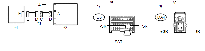
*1 |
Front Airbag Sensor RH |
*2 |
Center Airbag Sensor Assembly |
|
*3 |
Engine Room Main Wire |
*4 |
Instrument Panel Wire |
|
*5 |
Front view of wire harness connector (to Center Airbag Sensor Assembly) |
*6 |
Front view of wire harness connector (to Engine Room Main Wire) |
|
*7 |
Connector B |
*8 |
Connector C |
| OK | |
REPLACE ENGINE ROOM MAIN WIRE |
| NG | |
REPLACE INSTRUMENT PANEL WIRE |
|
8. |
CHECK INSTRUMENT PANEL WIRE (SHORT) |
|
(a) Disconnect the instrument panel wire connector from the engine room main wire. |
|
(b) Measure the resistance according to the value(s) in the table below.
Standard Resistance:
|
Tester Connection |
Condition |
Specified Condition |
|---|---|---|
|
DA4-1 (+SR) - DA4-2 (-SR) |
Always |
1 MΩ or higher |
|
*1 |
Front Airbag Sensor RH |
|
*2 |
Center Airbag Sensor Assembly |
|
*3 |
Engine Room Main Wire |
|
*4 |
Instrument Panel Wire |
|
*5 |
Front view of wire harness connector (to Engine Room Main Wire) |
|
*6 |
Connector C |
| OK | |
REPLACE ENGINE ROOM MAIN WIRE |
| NG | |
REPLACE INSTRUMENT PANEL WIRE |
|
9. |
CHECK INSTRUMENT PANEL WIRE (SHORT TO B+) |
|
(a) Turn the ignition switch off. |
|
(b) Disconnect the cable from the negative (-) battery terminal, and wait for at least 90 seconds.
(c) Disconnect the instrument panel wire connector from the engine room main wire.
(d) Connect the cable to the negative (-) battery terminal.
(e) Turn the ignition switch to ON.
(f) Measure the voltage according to the value(s) in the table below.
Standard Voltage:
|
Tester Connection |
Switch Condition |
Specified Condition |
|---|---|---|
|
DA4-1 (+SR) - Body ground |
Ignition switch ON |
Below 1 V |
|
DA4-2 (-SR) - Body ground |
Ignition switch ON |
Below 1 V |
|
*1 |
Front Airbag Sensor RH |
|
*2 |
Center Airbag Sensor Assembly |
|
*3 |
Engine Room Main Wire |
|
*4 |
Instrument Panel Wire |
|
*5 |
Front view of wire harness connector (to Engine Room Main Wire) |
|
*6 |
Connector C |
| OK | |
REPLACE ENGINE ROOM MAIN WIRE |
| NG | |
REPLACE INSTRUMENT PANEL WIRE |
|
10. |
CHECK INSTRUMENT PANEL WIRE (SHORT TO GROUND) |
|
(a) Disconnect the instrument panel wire connector from the engine room main wire. |
|
(b) Measure the resistance according to the value(s) in the table below.
Standard Resistance:
|
Tester Connection |
Condition |
Specified Condition |
|---|---|---|
|
DA4-1 (+SR) - Body ground |
Always |
1 MΩ or higher |
|
DA4-2 (-SR) - Body ground |
Always |
1 MΩ or higher |
|
*1 |
Front Airbag Sensor RH |
|
*2 |
Center Airbag Sensor Assembly |
|
*3 |
Engine Room Main Wire |
|
*4 |
Instrument Panel Wire |
|
*5 |
Front view of wire harness connector (to Engine Room Main Wire) |
|
*6 |
Connector C |
| OK | |
REPLACE ENGINE ROOM MAIN WIRE |
| NG | |
REPLACE INSTRUMENT PANEL WIRE |
 Center Airbag Sensor Assembly Malfunction (B1000/31)
DESCRIPTION
The center airbag sensor assembly consists of a deceleration sensor, safing sensor,
drive circuit, diagnosis circuit, ignition control, etc.
If the center airbag sensor assembly receiv ...
 Front Airbag Sensor RH Malfunction (B1610/13)
DESCRIPTION
The front airbag sensor RH circuit consists of the center airbag sensor assembly
and front airbag sensor RH.
The front airbag sensor RH detects impacts to the vehicle and sends signals ...
Other materials about Toyota Venza:
Speaker Output Short (B15C3)
DESCRIPTION
This DTC is stored when a malfunction occurs in the speakers.
DTC No.
DTC Detection Condition
Trouble Area
B15C3
A short is detected in the speaker output circuit.
...
Removal
REMOVAL
PROCEDURE
1. REMOVE FRONT SEAT HEADREST ASSEMBLY
2. REMOVE FRONT SEAT REAR OUTER TRACK COVER
3. REMOVE FRONT SEAT REAR INNER TRACK COVER
4. REMOVE FRONT SEAT ASSEMBLY
5. REMOVE SLIDE AND VERTICAL POWER SEAT SWITCH KNOB
6. REMOVE RECL ...
Motor Circuit Malfunction (C1521,C1531-C1534,C1554)
DESCRIPTION
If the power steering ECU detects these DTCs, it will shut off the motor relay
circuit (built into the power steering ECU) and stop power assist. However, power
assist continues if DTC C1533 or C1534 is stored.
DTC No.
D ...

0.129